JAA78071-R.3583.A
- L17 ・ AF-S 24-85/3.5-4.5G -
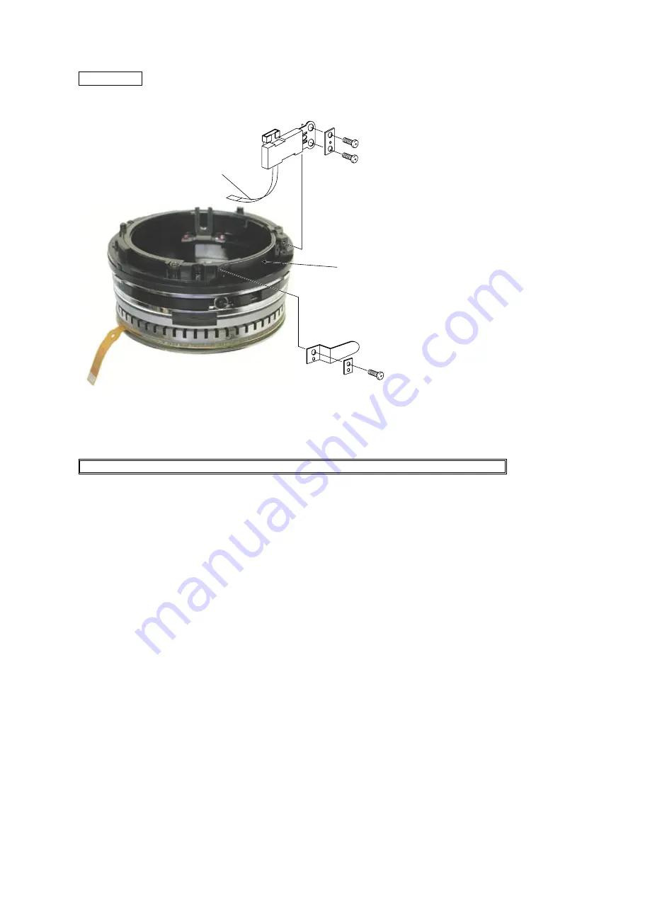
MR HEAD
# 541 × 2
# 534
# 533
# 536
# 543
MR head
①
Set the MR head to be parallel with the
magnetic tape.
②
Adhere the MR sensor FPC to the inside
of the SWM unit.
Note:
Adhere the MR sensor FPC not to be
sharply loosened.
Magnetic tape
MR sensor FPC
SWM unit
INSPECTION AND ADJUSTMENT FOR THE WAVEFORM OUTPUT FROM MR ENCODER
●
In case of disassembling or replacing the MR head, be sure to conduct adjustment.
1.
Equipment and tools to be required
・
Single output rated voltage power supply: 1 unit With 5.0V and 100mA, applicable to the self-made tool
・
Oscilloscope: 1 unit
・
Self-made tool: 1 unit
Note:
自
In case of any trouble in continuity between the self-made tool and the contacts of relay FPC, there may
be dust, corrosion or oxidation on the contact surface of relay FPC. Be sure to polish the contact surface prior to
getting connected with the self-made tool.
2.
Preparation for the lens to be measured
・
Set the SWM unit on which the MR head has already been set and the MF ring into the cam ring unit.
Then, connect to the measuring devices. (Refer to the next page.)
Summary of Contents for AF-S Zoom-Nikkor ED 24-85mm f/3.5-4.5G IF
Page 8: ...JAA78071 R 3583 A L6 AF S 24 85 3 5 4 5G SWM UNIT 96 3 B31 96 3 SWM unit ...
Page 13: ...JAA78071 R 3583 A L11 AF S 24 85 3 5 4 5G CAM RING 50 50 ...
Page 24: ...JAA78071 R 3583 A L22 AF S 24 85 3 5 4 5G 96 3 3rd LENS GROUP 3rd lens group ...
Page 46: ...JAA78071 R 3583 A F1 AF S 24 85 3 5 4 5G 外観図 Sketch drawings ...
Page 47: ...JAA78071 R 3583 A F2 AF S 24 85 3 5 4 5G 組立図 Structure of the Lens ...


