background image

VAA31001-R.3651.A

- A14 ・ E5600 -

LENS UNIT

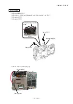
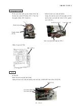
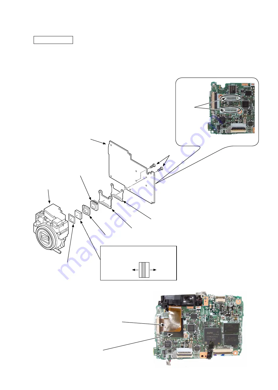
 Set the spacer LPF [#

209

] and the optical filter [#

210

] into the lens unit.

 As taking care about its direction, set the spacer [#

211

] into the lens unit.

 Set the spacer insulator [#

214

], the lens mount [#

213

] and the CCD [#

212

] and solder them to the main PCB CP-

1


[#

218

]. (Fig. 

1

)

 Tighten the two screws [#

106

].

 Adhere the spacer [#

225

].

 Set the FPC.

FPC

Spacer [#

225

]

(Fig. 

1

)

Perform 
soldering.

Optical filter [#

210

]

Setting direction

Lens unit side

CCD 
side

Screw [#

106

]

CCD [#

212

]

Spacer insulator [#

214

]

Lens mount [#

213

]

Spacer LPF [#

209

]

Spacer [#

211

]

Main PCB CP-

1

 [#

218

]

Lens unit

Summary of Contents for Coolpix 5600

Page 1: ...作成承認印 配布許可印 Copyright c 2005 by Nikon Corporation All Rights Reserved 無断転載を禁ず Printed in Japan February 2005 VAA31001 R 3651 A REPAIR MANUAL VAA31001 ...

Page 2: ...1 PCB D11 CONDENSER HOLDER D11 LENS UNIT D12 Points to notice when disassembling re assembling Lens unit D13 Tools required for FFD inspection and adjustment D13 FINDER UNIT D14 ZOOM MOTOR UNIT D14 DISASSEMBLY OF ZOOM MOTOR UNIT D15 CCD FRAME D16 BARRIER UNIT D17 FIXED BARREL D18 DISASSEMBLY OF FIXED BARREL D18 2ND LENS GROUP UNIT D19 SHUTTER D19 STRAIGHT BARREL D19 KEY BARREL TURN BARREL D20 1ST ...

Page 3: ...FINDER UNIT A12 Resolution inspection A13 LENS UNIT A14 CONDENSER HOLDER A15 TB 1 PCB A15 WIRE HOLDER A16 SB UNIT A16 A18 MONITOR HOLDER A18 MICROPHONE A19 SPEAKER HOLDER A20 LCD A20 TRIPOD SOCKET A21 ASSEMBLY OF FRONT COVER A21 A22 FRONT COVER A23 ASSEMBLY OF REAR COVER A23 REAR COVER A24 ADJUSTMENT A25 A35 DISCRIPTION OF CIRCUIT E1 E8 ELECTRICITY OVERALL WIRING E9 CP1 DMA CIRCUIT DIAGRAM E10 CP1...

Page 4: ... TB2 CIRCUIT DIAGRAM E17 OVERALL BLOCK DIAGRAM E18 CCD BLOCK DIAGRAM E19 LENS BLOCK DIAGRAM E20 ASIC BLOCK DIAGRAM E21 SYSTEM CONTROL BLOCK DIAGRAM E22 POWER BLOCK DIAGRAM E23 FUSE arrangement CP1 PCB E24 INSPECTION STANDARDS R1 R10 Tool List T1 T5 ...

Page 5: ...ertical Monitor Frame coverage shooting mode 1 8 80 000 dot amorphous silicon TFT LCD monitor Approximately 97 horizontal and 97 vertical Storage Media File system File formats Internal memory 14 MB SD memory cards Compliant with Design Rule for Camera File System DCF Exif 2 2 and Digital Print Order Format DPOF Compressed JPEG baseline compliant Movies QuickTime Exposure Metering Exposure control...

Page 6: ...eries Two FR6 L91 AA lithium batteries EH 62B AC adapter Number of frames taken in succession 220 frames alkaline batteries 340 frames EN MH1 600 frames lithium batteries Measured at standard temperature 25 77 F with fully charged batteries based on CIPA standard zoom adjusted with each shot flash used in approximately one half of shots image type set to Normal Dimensions W H D 85 60 35 mm 3 3 2 4...

Page 7: ...with traditional solder Use the special soldering iron respectively for lead free solder and lead solder They cannot be used in common Note Be sure to remove the SD memory card and batteries before disassembly When disassembling make sure to memorize the processing state of wires screws to be fixed and their types etc Because electrical parts are easily damaged by static electricity make sure that...

Page 8: ...the USB cover 033 As pushing the top side of the rear cover unit 030 by your finger perform unhooking Open the rear cover unit 030 slowly backward and remove the FPC Remove the USB cover 033 Rear cover unit 030 FPC Push Rear cover unit 030 Screw 103 USB cover 033 USB cover 033 Screw 102 Screw 102 ...

Page 9: ...A31001 R 3651 A D3 E5600 Remove the screw 104 Remove the earth shaft 029 Remove the cover shaft 009 Remove the SD cover 037 DISASSEMBLY OF REAR COVER Earth shaft 029 Screw 104 SD cover 037 Cover shaft 009 ...

Page 10: ...VAA31001 R 3651 A D4 E5600 Discharging of main condenser 2KΩ 5W ...

Page 11: ...51 A D5 E5600 FRONT COVER Remove the solder at 2 places Remove the FPC Remove the two screws 102 The earth release 026 can be removed Remove the front cover 013 Front cover 013 Screw 102 FPC Solder Earth release 026 ...

Page 12: ...VAA31001 R 3651 A D6 E5600 DISASSEMBLY OF FRONT COVER Remove the decoration top 021 Decoration top 021 Remove the two screws 104 Unhook the battery holder 024 Screw 104 Battery holder 024 Hook ...

Page 13: ...over 011 Take off the spacer 019 from the release button unit In the figure below the spacer is divided into three pieces from the dotted line Remove the screw 104 Remove the release button unit 020 DC cover spring 012 DC cover 011 Spacer 019 Screw 104 Release button unit 020 ...

Page 14: ...hered with the double adhesive tape Remove the FPC Remove the LCD 239 SPEAKER HOLDER Take off the spacer 206 Unsolder the lead wires red and white As turning counterclockwise remove the speaker holder 233 Tripod socket 201 Lead wires red and white FPC LCD 239 Spacer 206 Hook LCD 239 Speaker holder 233 Lead wire red Lead wire white Float this section and remove it as turning ...

Page 15: ...ake off the spacer 223 Remove the microphone 222 MONITOR HOLDER Remove the two screws 102 Remove the earth release 228 Remove the three screws 104 Remove the LCD holder 231 Microphone 222 Spacer 223 Spacer 025 Lead wire black Lead wire red LCD holder 231 Screw 104 Screw 102 Earth release 228 Screw 102 ...

Page 16: ...e spacer 039 Unsolder the lead wires gray and white Unsolder the lead wire black Unsolder the lead wire pink Remove the screw 104 Float the flash unit 219 Spacer 039 Lead wire black Lead wire pink Screw 104 Flash unit 219 Lead wires gray and white ...

Page 17: ...215 TB 1 PCB Perform unhooking and remove the TB 1 PCB 216 CONDENSER HOLDER Remove the connector Take off the spacer 224 Remove the screw 102 Remove the condenser holder 204 Hook TB 1 PCB 216 Wire holder 215 Connector Spacer 224 Screw 102 Condenser holder 204 Screw 102 Wire holder 215 ...

Page 18: ...he spacer LPF 209 the optical filter 210 and the spacer 211 can be removed Remove the solder fixing the CCD Fig 1 Remove the CCD 212 the lens mount 213 and the spacer insulator 214 Fig 1 FPC Spacer 225 Solder Screw 106 CCD 212 Spacer insulator 214 Lens mount 213 Spacer LPF 209 Optical filter 210 Spacer 211 Lens unit Main PCB CP 1 218 ...

Page 19: ...make a replacement 1st lens group unit 2nd lens group unit 3rd lens group unit Tools required for FFD inspection and adjustment Note When the operation check and adjustment of the lens unit are made for repairing the lens unit singularly the following tools are required Lens unit checking tool J61202 Connection cable for lens J61202F PCI I F board J61204 Connection cable for PC J61204A Adjusting f...

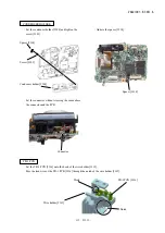
Page 20: ... ZOOM MOTOR UNIT Remove the solder of the motor at 2 places Remove the solder of the FPC at 4 places Remove the screw 430 Remove the zoom PI Remove the screw 429 Remove the screw 431 Remove the zoom motor unit Screw 429 Screw 431 Remove the solder Zoom motor unit 405 Screw 429 Zoom PI Screw 430 ...

Page 21: ...NIT Pull out the gear shaft D 419 Remove the zoom gear E 411 Remove the screw 429 and then remove the gear cover 403 Remove the zoom gear D 410 and the zoom gear C 409 Zoom gear E 411 Gear shaft D 419 Screw 429 Gear cover 403 Zoom gear D 410 Zoom gear C 409 ...

Page 22: ...16 E5600 CCD FRAME Remove the solder Remove the screw 430 Remove the four screws 431 Remove the lens barrel unit The finder gear B 417 can be removed Screw 431 Screw 431 Screw 430 Solder Lens barrel unit Finder gear B 417 ...

Page 23: ...rning counterclockwise Insert tweezers into the clearance and turn the barrier unit counterclockwise It will be removed easily Remove the barrier ring spring 420 Remove the barrier ring 404 by turning clockwise Name plate seal 415 Barrier ring spring 420 Barrier ring 404 Clearance Barrier unit 407 Clearance ...

Page 24: ...el 402 DISASSEMBLY OF FIXED BARREL Pull out the gear shaft A 413 and remove the zoom gear F 412 Pull out the gear shaft B 418 and remove the finder gear A 416 Remove the light shield ring 424 FPC sheet 423 Push out Turn barrel 401 Shutter FPC Gear shaft A 413 Gear shaft B 418 Zoom gear F 412 Finder gear A 416 Light shield ring 424 Turn barrel 402 ...

Page 25: ...the limit The 2nd lens group unit 426 floats a little and can be removed SHUTTER Remove the two screws 431 Remove the shutter unit 432 STRAIGHT BARREL 2nd lens group unit 426 Key barrel unit 428 Push out Straight barrel unit 427 Push out and remove the straight barrel unit 427 Screw 431 Shutter unit 432 ...

Page 26: ...EL Pull out the key barrel unit 428 from the turn barrel 401 1ST LENS GROUP UNIT Turn the 1st lens group unit 425 counterclockwise The 1st lens group unit 425 can be removed 1st lens group unit 425 Shading ring 424 Turn barrel 401 Key barrel unit 428 ...

Page 27: ...se to be installed correctly Apply the adhesive 1401B to 3 places KEY BARREL TURN BARREL There is a convex section on the side without gear on the turn barrel 401 Fit the lever position on the key barrel unit 428 to this convex section and set the key barrel unit 428 into the turn barrel 401 1st lens group unit 425 Straight barrel unit 427 1401B Turn barrel 401 Key barrel unit 428 Lever Convex sec...

Page 28: ...rrel unit 428 at the front side Set the long hole of the straight barrel unit 427 at the left side Fit the convex sections to the grooves and then set the straight barrel unit 427 into the key barrel unit 428 Straight barrel unit 427 Key barrel unit 428 Long hole Convex section Convex section Groove Groove Lever Screw 431 Shutter unit 432 ...

Page 29: ...sections to the grooves and set the 2nd lens group unit 426 into the key barrel unit 428 ASSEMBLY OF FIXED BARREL Set the light shield ring 424 Make the stepped difference side of the finder gear A 416 face the CCD Then set the finder gear A 416 and insert the gear shaft B 418 Set the zoom gear F 412 and insert the gear shaft A 413 Apply the adhesive EC 1368 to the gear shafts Gear shaft A 413 Gea...

Page 30: ... into the hole on the side of the fixed barrel 402 Fit the convex sections on the turn barrel 401 to the grooves on the fixed barrel 402 Set the turn barrel 401 into the fixed barrel 402 FPC sheet 423 Turn barrel 401 Shutter FPC Fixed barrel 402 Groove Convex section Convex section Groove ...

Page 31: ...Then install the lens barrel unit Tighten the four screws 431 Insert the FPC of the CCD frame into the boss Insert the shutter FPC into the boss Tighten the screw 430 Perform soldering Screw 431 Screw 431 Lens barrel unit Finder gear B 417 Screw 430 Solder Shutter FPC FPC of CCD frame Boss ...

Page 32: ...R UNIT Set the zoom gear C 409 and the zoom gear D 410 Set the gear cover 403 and tighten the screw 429 Screw 429 Gear cover 403 Zoom gear D 410 Zoom gear C 409 Set the zoom gear E 411 and insert the gear shaft D 419 Zoom gear E 411 Gear shaft D 419 ...

Page 33: ...e CCD frame and set it Tighten the screw 430 Solder the FPC at 4 places Solder the motor at 2 places Screw 429 Screw 431 Perform soldering Zoom motor unit Tighten the screw 429 Tighten the screw 431 Fold the FPC of the zoom PI as shown below and insert the zoom PI 1 2 3 Zoom PI Screw 430 ...

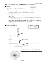
Page 34: ...by using the dial gauge etc 4 Based on the above 0 position turn the knob of the Adjuting focus stand further to set the 2 16 mm position 5 Press the reset button of the Adjusting focus stand again and set the 0 position Preparation FFD Inspection and adjustment FFD Flange Focal Distance FFD inspection and adjustment Turn the objective glass of the collimator J19019 and set degree to 0 0 mm Lens b...

Page 35: ...ns barrel unit on the Adjusting focus stand After mounting the lens barrel unit on the Adjusting focus stand connect wires J61202F of the lens unit inspection tool J15327A J15327D Lens barrel unit Adjusting focus stand for APS J15327 Connect wires J61202F ...

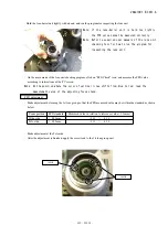
Page 36: ...e If the lens barrel unit is held too tightly the FFD value cannot be measured correctly Note Refer to supplied user manuals of the lens unit checking tool for how to run the program for inspecting the lens unit Note At the position where the color of vertical lines shifts from blue to red read the measurement value of the adjusting focus stand Zoom position FFD standard Measured value in relation...

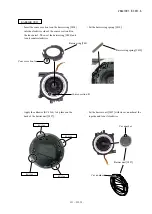
Page 37: ...rier ring 404 and turn it counterclockwise Barrier ring 404 Convex section A Convex section B Set the barrier ring spring 420 Barrier ring spring 420 Apply the adhesive EC 1368 to 4 places on the back of the barrier unit 407 EC 1368 EC 1368 EC 1368 EC 1368 Set the barrier unit 407 with its cav number at the top side and turn it clockwise Barrier unit 407 Cav number Cav number ...

Page 38: ...the operation with the lens barrel driving software at the service facilities equipped with the lens unit checking tool Set the finder unit 405 at the W end manually Install the finder unit 405 Tighten the three screws 429 405 Screw 429 Adhere the name plate seal 415 Name plate seal 415 ...

Page 39: ...e TV screen a To take pictures set the camera as follows Shooting mode AUTO Image quality mode High Flash mode Flash cancel b Check the zoom position at WIDE MIDDLE and TELE The object distance WIDE approx 0 53 m MIDDLE approx 1 23 m and TELE approx 1 6 m Set the chart fully screened in the LCD of the camera and fix it on a tripod c Open the shot image by Photoshop and confirm it by the magnified ...

Page 40: ... Set the spacer insulator 214 the lens mount 213 and the CCD 212 and solder them to the main PCB CP 1 218 Fig 1 Tighten the two screws 106 Adhere the spacer 225 Set the FPC FPC Spacer 225 Fig 1 Perform soldering Optical filter 210 Setting direction Lens unit side CCD side Screw 106 CCD 212 Spacer insulator 214 Lens mount 213 Spacer LPF 209 Spacer 211 Main PCB CP 1 218 Lens unit ...

Page 41: ...ut crossing the cords above the connector and the PCB TB 1 PCB Adhere the spacer 224 Spacer 224 Screw 102 Condenser holder 204 Spacer 224 Connector Hook TB 1 PCB 216 Wire holder 215 Notch Set the TB 1 PCB 216 onto the hook of the wire holder 215 Pass the lead wire of the TB 1 PCB 216 through the notch of the wire holder 215 ...

Page 42: ... tighten the screw 102 Screw 102 Wire holder 215 SB UNIT Arrange the lead wires pink and blue as shown below As arranging the lead wire blue as shown below Fig 1 set the flash unit 219 and tighten the screw 104 Fig 2 Fig 1 Fig 2 Lead wire blue Screw 104 Flash unit 219 ...

Page 43: ...e the lead wire pink as shown below Solder the lead wire pink Lead wire pink Lead wire pink Solder the lead wires gray and white Solder the lead wire black Lead wire black Arrange the lead wires as shown below Lead wires gray and white ...

Page 44: ...er 039 Spacer 039 MONITOR HOLDER Fit the LCD holder 231 to the bosses set it and tighten the three screws 104 Set the earth release 228 Tighten the two screws 102 LCD holder 231 crew 104 Screw 102 Earth release 228 Screw 102 Boss Screw 104 Boss ...

Page 45: ...nd red MICROPHONE Set the microphone 222 Set the lead wires black and red onto the hook without crossing them Fig 1 Set the spacer 223 Set the spacer 025 Microphone 222 Spacer 223 Spacer 025 Set the lead wires onto the hook Fig 1 Lead wire black Lead wire red ...

Page 46: ...er 206 Fit the center boss on the speaker holder 233 into the boss hole on the LCD holder 231 Then turn the speaker holder 233 clockwise LCD Set the FPC Solder the lead wires red and white Arrange the lead wires red and white as shown below Fold the FPC and set the LCD 239 Speaker holder 233 Boss hole position Lead wire white Lead wire red of microphone 222 Lead wire red Lead wires white Lead wire...

Page 47: ...ighten the screw 104 ASSEMBLY OF FRONT COVER Adhere the spacer 019 of the release button unit as shown below The spacer 019 is divided into three pieces from the dotted line in the figure Set the DC cover 011 DC cover 011 Set the DC cover spring 012 DC cover spring 012 Tripod socket 201 Hook Convex section A Notch B Screw 104 Release button unit 020 Spacer 019 LCD 239 Set the convex section at the...

Page 48: ...VAA31001 R 3651 A A22 E5600 Set the battery holder 024 by using the hook Tighten the two screws 104 Set the decoration top 021 Decoration top 021 Screw 104 Battery holder 024 Hook ...

Page 49: ...02 Perform soldering Set the FPC Set the front cover 013 Front cover 013 Screw 102 FPC Perform soldering Earth release 026 Set the SD cover 037 Set the cover shaft 009 Set the earth shaft 029 Tighten the screw 104 ASSEMBLY OF REAR COVER Earth shaft 029 Screw 104 SD cover 037 Cover shaft 009 ...

Page 50: ...he FPC as shown below and set it FPC Rear cover unit 030 Set the USB cover 033 REAR COVER Tighten the two screws 103 Set the rear cover unit 030 Rear cover unit 030 Tighten the four screws 102 USB cover 033 Screw 102 Screw 102 Screw 103 ...

Page 51: ...ware 3 Adjustment items and order Adjustment after replacing the CP 1 PCB of RP 1 Writing of the initial image data 2 Firmware up 3 Lens adjustment 4 AWB adjustment 5 CCD white dot defect compensation 6 CCD black dot white dot defect adjustment 7 USB storage information registration Note If replacing the lens CCD optical filter it is necessary to perform the above 3 7 adjustments again 4 6 adjustm...

Page 52: ...only firmware upgrading is performed without replacing CP 1 PCB copying nanddat bin into the SD card is NOT necessary Procedure Turn the camera OFF and connect the AC adapter Insert the upgrading SD card into camera Set the mode dial to SETUP and turn power ON Highlight and select Firmware version to display the menu for data writing of initial images Fig 1 Write the data of initial images and go ...

Page 53: ...ct Yes and press the decision button to carry out upgrading Fig 4 Note Do NOT turn power OFF during upgrading When the screen indicates the completion of upgrading turn power OFF and remove the SD card Fig 5 Turn power ON and check the version by Firmware version on the menu Turn power OFF to end Fig 3 Fig 5 Fig 4 ...

Page 54: ...drive with 15 MB or more memory space VGA or SVGA monitor with 256 or more color display 2 Installing calibration software Insert the calibration software installation diskette into the diskette drive Open Explorer Copy DscCalDi exe Camapi32 dll folder of the floppy disk drive in any folder on the hard disk 6 Installing USB driver If the USB driver is necessary install Nikon View via CD ROM packed...

Page 55: ...sion plate with the Color Meter J63081 2 Adjust the pattern box so that the color temperature should be 3100 20K by using VR for adjustment of the color temperature 3 Measure the center of the diffusion plate with the Luminance Meter BM 3000 J63068 4 Adjust the pattern box so that the luminance should be 900 20cd m2 by using Knob for luminance adjustment 5 Repeat from 1 to 4 So that the color temp...

Page 56: ...e camera s USB port 2 Connect the cable to the USB port on PC 10 Calibration software Turn on the power switch of the camera When the calibration software starts the following is displayed on the PC monitor USBポートへ 電源はACアダプタEH 62B から供給してください USBケーブル UC E6 To USB port USB Cable UC E6 Supply the power through the AC adapter EH 62B ...

Page 57: ...e power switch of the camera to on Siemens star chart POWER switch of camera ON Conditions Set the adjustment collimator and the camera front surface of lens at the nearest distance between them How to Double click on DscCa1Di exe Set the siemens star chart so that it comes center of the screen by checking through the viewfinder Click Focus then Yes Lens adjustment value will appear on the screen ...

Page 58: ...CaDi140 and click Firmware on the main menu to write the product firmware Preparations Set the Siemens star chart Turn the power switch of the camera to on Conditions The siemens star chart should be A3 size or larger Copy and enlarge A4 size siemens chart included in the service manual for the usage Illumination over the object should be 400 lux 10 Set the siemens star chart and the camera front ...

Page 59: ...ns Set the pattern box and camera lens front at 0cm distance between them Note Do not allow outside light to enter in How to Double click on DscCa1Di exe Click AWB then Yes AWB adjustment values will appear on the screen Judgment standard CHECK 128 1 128 1 130 40 Click OK カメラ バターンボックス Yes Result of adjustment Camera Pattern Box ...

Page 60: ...CD black dot white dot defect adjustment Conditions Fix the camera so that only the white part of the pattern box should be displayed on the screen Do not allow outside light to enter in as much as possible With the lens shutter being opend read the defect black dots of CCD pixels Then make the correction data and rewrite the data by the following procedure Correct the upper level of defective 256...

Page 61: ...the camera to a computer Double click on the DscCa1Di exe Click on the Get button in the USB storage window and check the USB storage data VID NIKON PID NIKON DSC E5600 Serial Rev 1 00 Check the Serial in the above USB storage data If the displayed value is different from the serial number printed on the base of the camera enter the number on the base of the camera and click the Set button Check V...

Page 62: ...VAA31001 R 3651 A E1 E5600 ...

Page 63: ...VAA31001 R 3651 A E2 E5600 ...

Page 64: ...VAA31001 R 3651 A E3 E5600 ...

Page 65: ...VAA31001 R 3651 A E4 E5600 ...

Page 66: ...VAA31001 R 3651 A E5 E5600 ...

Page 67: ...VAA31001 R 3651 A E6 E5600 ...

Page 68: ...VAA31001 R 3651 A E7 E5600 ...

Page 69: ...VAA31001 R 3651 A E8 E5600 ...

Page 70: ... 0C SCAN IN 0D SCAN IN 4D SCAN IN 1 AF LED G SB LED R SCAN IN 2C SCAN IN 1C SCAN IN 3D SCAN IN 1D SCAN OUT 3 SCAN IN 2D SCAN OUT 3 SCAN IN 4C SCAN OUT 2 SCAN OUT 1 SCAN OUT 0 SCAN IN 3C SCAN IN 2 SCAN IN 4 SCAN IN 3 SCAN IN 2 SCAN IN 3 AL 3 2V GND BK SP RD MIC RD SPEAKER TB2 TB1 LCD_AN RED LCD_CA WHITE CP1 GND 6 5 GND GND 4 GND 1 3 GND 2 GND LED BACK UP ST1 LCD PANEL SD LCD BACK LIGHT VIDEO USB LE...

Page 71: ...5 FD6 FD2 FD3 FD0 FD1 CDT0 FSIN1 FSIN2 PICTL FD4 FSMD2 CA0 ZWAIT ZIOWR FD7 AD9 AD8 AD11 AD10 AD4 AD6 AD5 AD0 AD1 AD3 AD2 AD7 TGVD TGHD SUBGT ADCK L3V LCDSCK LCDD02 LCDD00 LCDD01 LCDVD LCDD05 LCDHD LCDEN LCDCLK LCDSD LCDD03 LCDD04 ZSWP CRZB1 CA0 ZSCE ZIORD FD6 FD7 FD0 FD3 FD4 FD1 FD2 FD5 ADCK 12V L SA7 SA8 SA4 SA3 SA6 SA5 SA11 SA9 SA10 DQM2 SD31 SD28 SD27 SD30 SD29 DQM1 DQM0 SA0 ZRWE SA2 SA1 DQM3 L...

Page 72: ...DON PAON CHG BEEP SI0C SI4D SI0D AF LED G SB LED R SI1C SI1D SI0C SI0D SI2C SI2D SI3C SI3D SI4C SI4D BACKUPBAT SDO ZCARD VMONIT SO0 SO1 SO2 SO3 SO4 SI0 SI1 SI2 SCK SDI SI4 SI3 SI4C SI1D SI2D SI3D SI2C SI1C SI3C SI0E SI2E SI1E SO4 SO3 SO2 SO1 SO0 MRST SI0 SI1 SI2 SI4 SI3 ZAVJACK SB LED R AF LED G PW_LED TO CN301 TO CN302 BACKUPBAT BOOST4 25V UNREG CN301 C3001 VA308 R3014 C3007 C3006 CN302 VA303 VA3...

Page 73: ...5 R9016 IC903 C9027 RB903 RB901 L9003 L9004 R9005 C9017 XF901 C9013 L9002 R9006 C9035 D9004 R9014 C9036 CB904 0 1 16Z 470 1 16J 1 B AN20101A 3 3 1 16J 1 B 82K 1 16J 1 B 1 B 1 H 100K 1 16J 0 033 B MA4S111 MA2J727 BK1608LL241 T 1 B TK11130CS 1 B 10 6 3 T 0 1 16Z 0 1 16Z 100 0 1 B 47 1 16J 0 1 B 1 B AD9948 0 1 B 1000P B 0 15 B 2SC5661 P 0 1 16Z 1 2K 1 16D 47 1 16D MN39620 0 01 B 100 100 BLM15BB100 BL...

Page 74: ... C5024 D5006 D5003 R5013 D5004 R5015 R5018 C5026 R5016 C5002 C5004 C5006 R5007 C5005 C5009 C5008 R5019 R5021 R5020 F47K2R0C3LFND 2A 2A 2A 0 01 B 680K 1 16D RN1104FV 33 8 V FDC633N NF 412K 1 16D 3 6K 1 16D 130K 1 16D 22P CH 10 16B 10 B 150K 1 16D 47 M 47 M HN2D01JE 1 B 10K 1 16D 1 B 22 6 3B 10 M SD833 04 SC XC9104D095MP 33 6 3 1 RSR025N03 10K 1 16D 3 6K 1 16D 150K 1 16D 1K 1 16J 1000P B 22 M US5U2 ...

Page 75: ...05 R5414 R5409 R5406 C5407 R5408 R5413 D5407 Q5409 C5415 Q5406 R5426 R5432 D5406 D5408 D5405 R5421 C5408 C5416 C5414 Q5401 IC541 R5401 R5420 1AV4L17B0370N 1000P B 0 033 350H RR255LA 400 68 1 16J 100K 1 8J 91K 1 16D RR264M 400 220K 1 8J 10M 1 8F CRF02 Q 0 01 630H 22 6 3B 0 068 B 1AV4L17B0200G 0 01 B 3LN01S E CPH5504 E 1K 1 16J 1 2K 1 16J 100 1 16J 0 015 B 120 1 16J 10K 1 16J DAN222 GT8G133 3LN01S E...

Page 76: ...VAA31001 R 3651 A E15 E5600 ST1 回路図 ST1 CIRCUIT DIAGRAM JW551 BLACK JW552 LPK C5412 120u 300V CEXAG579121AN TO CP1 STA JM541 542 S1 68900 SX796 JNK ST1 MODEL E5600 CIRCUIT DIAGRAM ST1 ...

Page 77: ...01 R 3651 A E16 E5600 TB1 回路図 TB1 CIRCUIT DIAGRAM NEW OM ORLE07AZ H 0 8 CA AN JW601 JW602 TO CP1 SYA CL308 CL307 GRAY WHITE D6001 DLSML 511UW G SELF RED T1 68900 SX796 JNK TB1 MODEL E5600 CIRCUIT DIAGRAM TB1 ...

Page 78: ...VAA31001 R 3651 A E17 E5600 TB2 回路図 TB2 CIRCUIT DIAGRAM TO CP1 SYA CN303 OM ORZD20B07400HZ H 2 5 1 85 BOND WT BK Z6501 ML614 TZ14 1AV4D20B09300 T2 68900 SX796 JNK TB2 MODEL E5600 CIRCUIT DIAGRAM TB2 ...

Page 79: ...O SREQ CN301 IC301 8bit Micro Processor LENS DRIVER IC951 CN951 LENS 3 LENS BLOCK Z6501 TB2 FSEN FSMD 1 2 FSIN 1 2 PICTL ZMIN 1 2 ZPULSE 1 2 ZRESET FPI XSUB CCDCK CCDSD CCDEN SUBGT XV 1 6 TGVD TGHD ADCK AD 0 11 XSG 1A 2A 1B 2B 3 CCD BLOCK IC101 ASIC 5M Pixel IC903 V Driver IC901 IC905 CCD CDS AGC AD C H Driver USBD PADAOUT ASICAIN AUDIO CONTROL SIGNALS X 5 USBD Ni MH CP1 LCD BACKLIGHT LCD_AN LCD_C...

Page 80: ...R AN20101A XSG1B XSG3 SUB GT IC905 CDS A D C AD9948 D2 11 31 32 33 AD2 AD11 ADCK CCDCK CCDSD CCDEN VDC IC904 REG TK11130CS 3 0V 4 1 3 45V A VDD3 TO DMA MAIN IC101 ASIC 10 13 17 18 11 1 8 15 19 1 2 21 23 24 20 25 22 26 28 27 3 25 9 2 4 7 13 27 18 19 14 15 21 8 12V A 3 45V A 6 0V A 6 18 4 5 26 24 37 6 TGVD TGHD 34 35 17 22 H DRIVER 14 SUBSW 16 HL XV4 XSUB XSG2B V1 V2 V3A V3B V4 V5A V5B V6 MODEL E560...

Page 81: ...I CN951 UNIT LENS ZPULSE1 IC101 213pin ZMIN1 IC101 209pin ZMIN2 IC101 208pin FSEN IC101 203pin FSMDI IC101 202pin FSMD2 IC101 201pin FSIN1 IC101 200pin FSIN2 IC101 199pin FPI IC101 206pin SHUTTER SHUTTER IRIS IRIS 19 18 6 7 20 17 8 9 11 10 3 5 13 ZOOM_PI 16 Q9509 IC961 L9601 D9601 Q9601 C9603 SW REG BOOST4 25V ZRESET IC101 210pin Q9501 Q9502 ZPULSE2 IC101 212pin PIV 1 14 2 4 15 12 3 4 8 9 5 6 7 IN...

Page 82: ...PAL ENCODER SRAM BUS BUS DIGITAL I F A D D A TG CLKGEN PLL SDRAM CONTROLLER JPEG CONTROLLER CCD 98MHz 4fsc 36MHz 72MHz ARM UART USB SD PWM SIO IC301 MICRO PROCESSOR EXT PORT LENS DRIVER PIO BUS I F FLASH NOR SDRAM CCD BLOCK IC101 ASIC RGB 6bit DATA CCD DRIVER AUDIO DRIVER SD CARD USB CONNECTOR MODEL E5600 BLOCK DIAGRAM ASIC FLASH NAND ...

Page 83: ...REG VDD RESET ALWAYS3 2V IC304 RESET IC 4 3 1 2 OUT VDD VSS BACK UP SO AUTO 2nd MOVIE SW3 2V Q3001 TELE MENU DEL WIDE PW_TEST PLAY RIGHT LEFT UP DOWN CN302 CN301 CN301 CN302 TEST AVJACK BACKUP CTL SCAN OUT0 SB_LED R AF_LED G IC301 8bit MICRO PROCESSOR SCAN IN0 SCAN IN1 SCAN IN2 SCAN OUT1 SCAN OUT2 PW_LED RESET BAT OFF BATTERY SCAN IN3 SCAN IN4 AV REF ON AVREF SCAN OUT3 VDD VDD SCAN OUT4 SCK 36 MOD...

Page 84: ...PON_H 3 7V PON_L BOOST4 25V OUT4 OUT1M DRAIN2L DRAIN2H DRAIN3L L5004 Q5004 STEP UP CIRCUIT OUT6 L5007 STEP UP CIRCUIT CURRENT DETECTOR CIRCUIT IC502 REG OUT7B LCD_AN LCD_CA 58 62 63 19 20 17 53 6 7 4 5 10 11 16 15 51 55 34 MODEL E5600 BLOCK DIAGRAM POWER VR VR501 12V L PA ON2 LCDON BLON PON TO DMA MAIN TO DMA LCD TO DMA MAIN STA TO DMA MAIN LENS TO DMA MAIN LCD LENS TO LCD BACK LIGHT SWIN6 SWIN7 S...

Page 85: ...10 L5009 L5001 C5032 C5029 R5414 R5413 C5406 Q5407 D5407 C5407 Q5405 C5414 C5416 R5420 C5415 IC541 R5401 Q5401 R5423 D5007 C1905 R1902 C1904 C1004 C1003 C1018 C1002 R1002 RB104 C1519 R1103 C1101 Q1736 CB181 IC182 C1815 C1830 C1823 C1824 C1803 R1812 C1831 C1829 C1828 R1815 C1810 R1814 C1825 R1813 R1806 C1827 C1806 C1807 Q1735 R1735 R1736 R1811 R1801 C1820 C1821 C1822 IC181 C1512 C1505 C1515 R1503 R...

Page 86: ...VAA31001 R 3651 A E5600 The contents of inspection standards and tools for E5600 1 Inspection standards R1 to R10 2 Tools T1 to T5 ...

Page 87: ...s or irregular noise shall not be required Check it by shaking the camera while operating Lightly hit the camera onto the Linoleum laid desk while operating No cave ins of the buttons shall be required Operator must feel click on each button Click must occur when or after a switch is ON Check it while operating normally When clicking normal touch shall be required Any outstanding caught in mechani...

Page 88: ...5 8 2 3 Tele end position Compelling F4 9 10 6 2 1 Against the picture center the luminance of the nearest peripheral area must be 35 or more Against the picture center the luminance at 70 of the image height must be 55 or more There must not be an outstanding ghost flare There must not be an outstanding flare at the center There must not be an outstanding deformation There must not be an outstand...

Page 89: ...ation Tape measure EIAJ chart Siemens chart Shooting with a speed light Light adjustment accu racy Guide No FULL ISO100 m Recycling time Wrong flash Tele end 0 4 2 0m Wide end 0 4 3 3m Macro wide end 0 4 3 4 m In the above range 0 5 Ev or less Photography mode AUTO Speed light Compelling flash 6 8 0 4 EV Charge for 10 seconds with the new primarybattery and perform measurement within 1 second With...

Page 90: ...vertical 150 TV pcs 10 0 3m The whole zoom area Center horizontal vertical 1150 TV pcs 0 3 0 04m The whole zoom area Center horizontal vertical 950 TV pcs Take a picture on condition that aperture is open in the AUTO mode and image quality priority mode Equip the 5100K viewer with the chart with WIDE end MIDDLE Z08 TELE end and the distance of 0 3m or more and shoot an object in the full range of ...

Page 91: ... a chart at the distance of 2m set it in the out of focus condition and shoot it Use a white paper to set it in the out of focus condition EIAJ chart Photoshop Siemens chart Gradation luminance level Histogram s gray average value Black 12 5 Gray 130 15 White 225 10 Equip the 5100K viewer with a scale and shoot an object in the full range of angle of view while the AUTO mode and the image quality ...

Page 92: ...e histogram s gray standard deviation Measurement section Noise Upper left 2 step Black 6 steps Gray Lower left 6 steps Gray 10 steps Black 5100K viewer ITE γ 0 45 Gray scale standard Photoshop Reproduction of color Color R G B W 209 20 209 20 209 20 Ye 209 20 209 20 47 15 R 215 20 15 10 10 10 Equip the 5100K viewer with a chart and shoot an object in the full range of angle of view in the AUTO mo...

Page 93: ...proper range to operate the stamped line and visual field frame You can check the whole finder visual field The finder must be activated smoothly in a link operation with the lens barrel zooming action The position and quantity must be as follows Zone Size A B C Less than 10 μ m 0 pc 2pcs or less 3pcs or less 10 20 μ m 0 pc 0 pc 1pcs or less More than 20 μ m 0 pc 0 pc 0 pcs Visual observation Visu...

Page 94: ...nce and horizontal difference of the black belt width in the image periphery must be within 0 3mm Through the monitor image 96 to 100 Play back image 98 to 100 Perform reproduction for each single color of R G B and white and check visually 1 2 1 1 Zone A 2 Zone B 1 Zone Bright pixel Dim pixel A 1 6 B 3 Total 4 6 Bright pixels Visible normally through 5 ND filter Dim pixels Visible normally Standa...

Page 95: ... blinks There is no regulation of voltage Power OFF 2 425 0 1V 2 0 0 1V The battery mark blinks There is no regulation of voltage Power OFF Connect the constant voltage power supply to the dummy battery pack and decrease the power supply voltage 1 second before The voltage is under the following conditions now Measure the voltage excluding When voltage increases Level 1 The battery half mark light...

Page 96: ...t the constant voltage power supply to the dummy battery pack and check the voltage at Level 3 no battery capacity indication Then turn off the power increase the voltage by 0 1V and change the power switch from OFF to ON The voltage is under the following conditions now Measure the voltage When changing the voltage turn off the power Level 1 The battery mark is turned off on the monitor LCD Level...

Page 97: ... E8700 E4100 E4600 E5600 Common E4300 E3500 E3100 E2100 E5400 E3700 E3200 E2200 E8700 E4100 E4600 E5600 J63080A 交換用ハロゲンランプ LV 1450DC 用 Spare Harogen Lamp For LV 1450DC LV 1450DC Exclusive J63081 カラーメータ ミノルタカラーメータⅢ F Color Meter Minolta Color meter Ⅲ F 共通 Common J63068 輝度計 BM 3000 Luminance Meter BM 3000 共通 Common 2 工具一覧表 Tool List 新規工具 New tool POWER BM 3000 ...

Page 98: ...3700 E3200 E2200 E8700 E4100 E4600 E5600 Common E995 E775 E885 E5000 E2500 E4500 E5700 E4300 E3500 E3100 E2100 E5400 E3700 E3200 E2200 E8700 E4100 E4600 E5600 J63090 コリメータ C DSC Collimator C DSC 共通 Common サービスマニュアル添付 Attached in Service Manual ジーメンスチャート 共通 Common J63079 ITE 高精細解像度チャート 4 3 反射型 ITE HIGH RESOLUTION CHART 4 3 REFLECT TYPE 共通 Common 新規工具 New tool Collimator C DSC ...

Page 99: ... FFD 点検調整用 For FFD inspection and adjustment J61202F 接続コード Connection cable for lens FFD 点検調整用 For FFD inspection and adjustment J61204 デジタル通信ボード PCI I F board FFD 点検調整用 For FFD inspection and adjustment J61204A 通信ボード用ケーブル Connection cable for PC FFD 点検調整用 For FFD inspection and adjustment 新規工具 New tool ...

Page 100: ... inspection and adjustment J15327A FFD 調整用マイクロ台アダプター Adapter for J15327A FFD 点検調整用 For FFD inspection and adjustment J15327D FFD 調整用マイクロ台アダプター Adapter for J15327D FFD 点検調整用 For FFD inspection and adjustment J65072 E4600 E5600 鏡筒駆動ソフト E4600 E5600 lens unit checking program FFD 点検調整用 For FFD inspection and adjustment 新規工具 New tool ...

Page 101: ...VAA31001 R 3651 A T5 E5600 ジーメンススターチャート ...

Reviews: