VRA53801 - R.3609.A
-
A
3・
LS-50
-
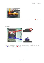
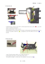
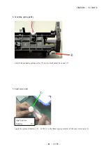
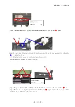
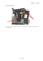
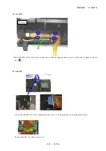
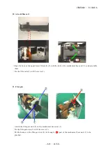
4. Scan motor unit
・
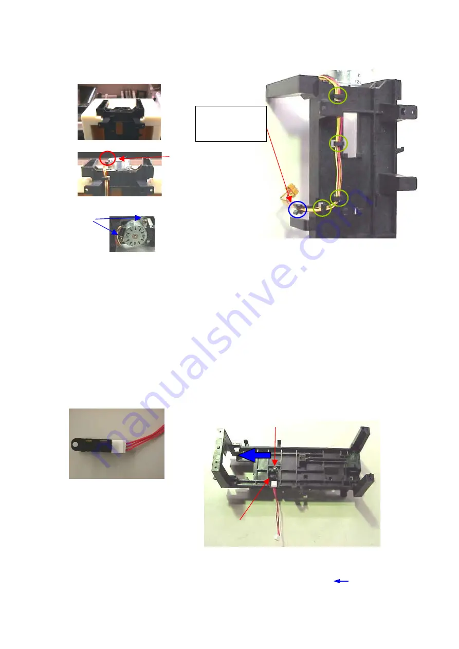
Attach the harness of the scan motor unit (1) on the mechanical base unit (1) so that (
〇
) part of the
harness is positioned at the left side.
・
Fix the scan motor unit (2) with 2 screws (3).
・
Hook the harness of the scan motor unit (2) to the claws of the backside of the mechanical base unit (1) at
the above 4 positions as shown by (
〇
) and pinch one part of the harness at the above (
〇
)
position.
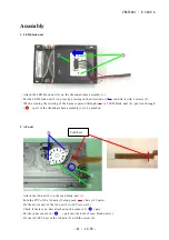
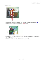
5. Photo interrupter
・
Connect the photo interrupter harness (2) to the photo interrupter (1).
・
Attach the photo interrupter (1) on the mechanical base unit (3).
・
Fix the photo interrupter (1) with the screw (4) by pressing it in the direction of (
).
③
②
①
②
①
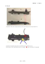
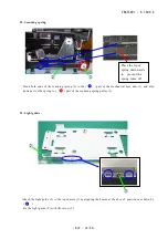
Twist once and
put here to be
pinched in.
③
③
①
④
①
②
Summary of Contents for COOLSCAN V ED
Page 77: ...VRA53801 R 3609 A ー E3 LS 50 ー メイン基板 1 Main PCB 1 ...
Page 78: ...VRA53801 R 3609 A ー E4 LS 50 ー メイン基板 2 Main PCB 2 ...
Page 79: ...VRA53801 R 3609 A ー E5 LS 50 ー メイン基板 3 Main PCB 3 ...
Page 80: ...VRA53801 R 3609 A ー E6 LS 50 ー メイン基板 4 Main PCB 4 ...
Page 81: ...VRA53801 R 3609 A ー E7 LS 50 ー メイン基板 5 Main PCB 5 ...


