VRA53801 - R.3609.A
- A
18 ・
LS-50 -
①
②
③
①
②
③
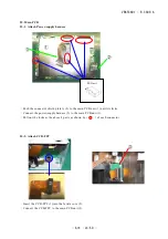
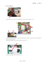
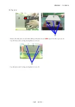
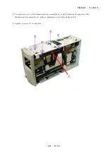
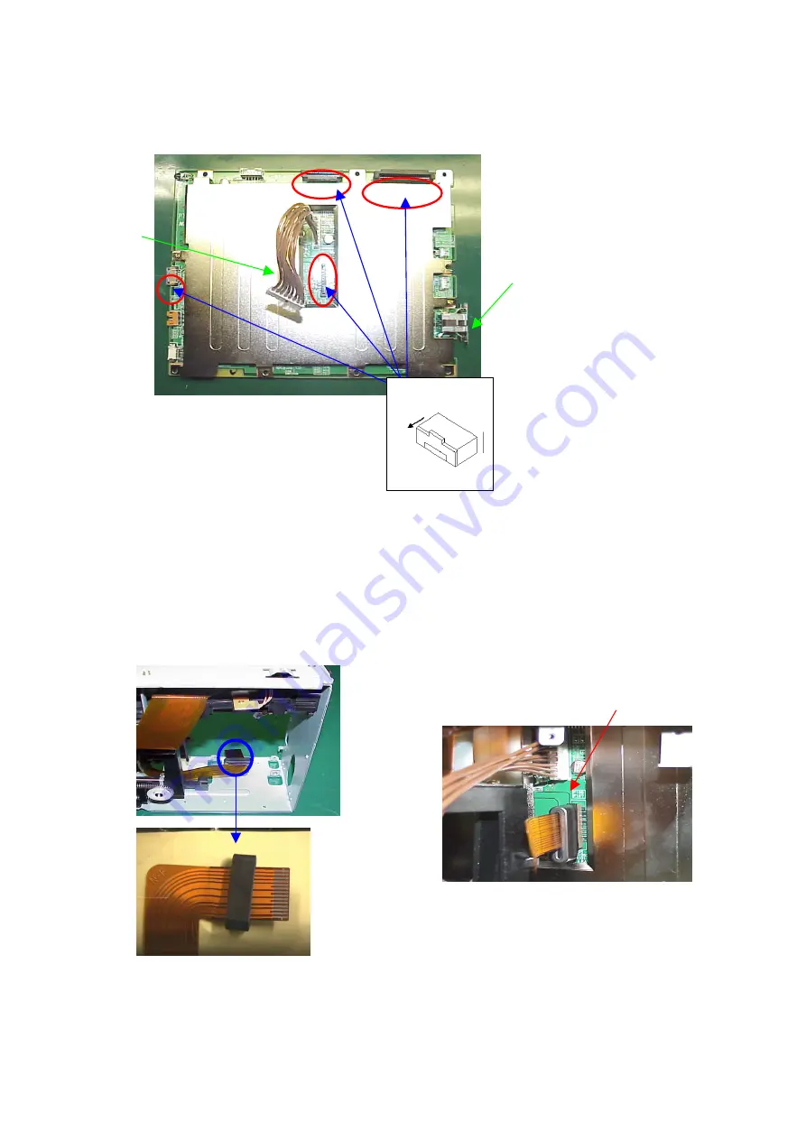
25. Main PCB
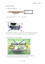
25-1. Attach Power-supply harness
・
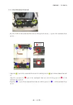
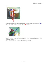
Push the connector shield plate A (2) to the main PCB unit (1) until it clicks.
・
Connect the power-supply harness (3) to the main PCB unit (1).
・
Pull out the locks at the above 4 parts as shown by (
〇
) of each connector.
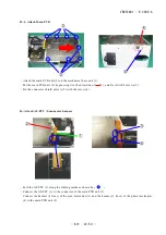
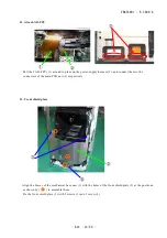
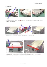
25-2. Attach CCD-FPC
・
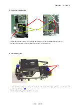
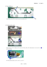
Insert the CCD-FPC (1) into the ferrite core (2).
・
Connect the CCD-FPC to the main PCB unit (3).
Pull out
Summary of Contents for COOLSCAN V ED
Page 77: ...VRA53801 R 3609 A ー E3 LS 50 ー メイン基板 1 Main PCB 1 ...
Page 78: ...VRA53801 R 3609 A ー E4 LS 50 ー メイン基板 2 Main PCB 2 ...
Page 79: ...VRA53801 R 3609 A ー E5 LS 50 ー メイン基板 3 Main PCB 3 ...
Page 80: ...VRA53801 R 3609 A ー E6 LS 50 ー メイン基板 4 Main PCB 4 ...
Page 81: ...VRA53801 R 3609 A ー E7 LS 50 ー メイン基板 5 Main PCB 5 ...

