VRA53801 - R.3609.A
- A
24 ・
LS-50 -
⑤
①
②
④-2
④-3
④-4
④-1
④
①
③
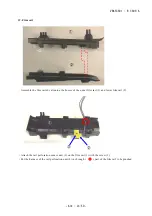
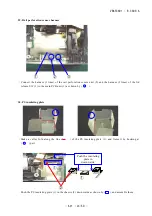
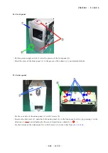
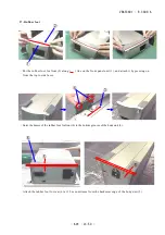
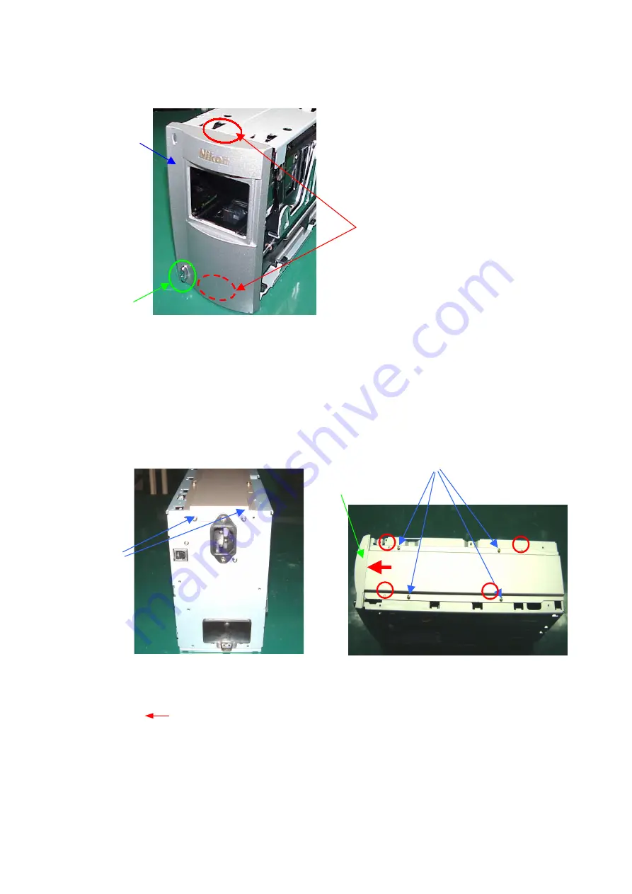
34. Front panel
・
Put the power-supply switch (2) into the groove of the front panel (1).
・
Hook the claw of the front panel (1) to the groove of the chassis (3), and assemble them.
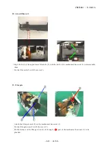
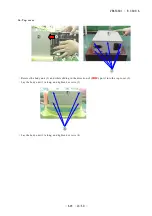
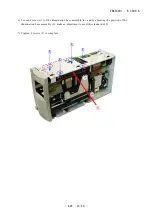
35. Under-panel
・
Fix the rear side of the under-panel (1) with 2 screws (2).
・
Reverse the body unit (3), and attach the under-panel (1) to the front-panel unit (4), by pressing it in the
direction of (
) and aligning the bosses at 4 positions as shown by (
〇
).
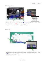
・
Fix the bottom of the under-panel (1) with 4 screws (5) in the order from
(4)-1
to
(4)-4
.
①
③
②
Summary of Contents for COOLSCAN V ED
Page 77: ...VRA53801 R 3609 A ー E3 LS 50 ー メイン基板 1 Main PCB 1 ...
Page 78: ...VRA53801 R 3609 A ー E4 LS 50 ー メイン基板 2 Main PCB 2 ...
Page 79: ...VRA53801 R 3609 A ー E5 LS 50 ー メイン基板 3 Main PCB 3 ...
Page 80: ...VRA53801 R 3609 A ー E6 LS 50 ー メイン基板 4 Main PCB 4 ...
Page 81: ...VRA53801 R 3609 A ー E7 LS 50 ー メイン基板 5 Main PCB 5 ...

