


Chapter 5 Laser Unit
5.4 LU4A Four-laser Module A
1-174
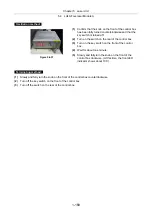
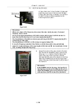
Figure 5.4-47
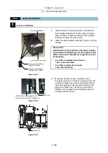
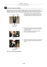
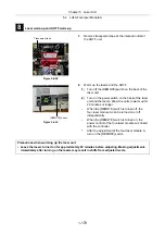
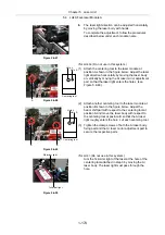
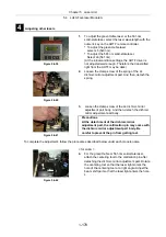
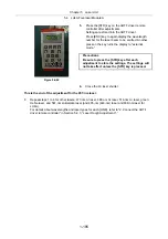
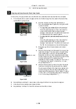
6.
The laser light direction can be adjusted horizontally
by moving the laser body with hands.
To complete the adjustment, follow the procedures
described below under each module name.
Figure 5.4-48
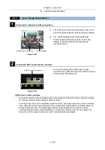
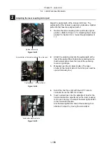
Figure 5.4-49
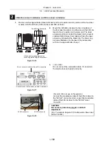
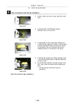
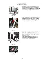
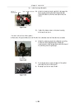
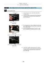
<for LU4A> (Do not use in this system.)
(1) Attach the centering tool to the laser module at
position A shown in the figure below. Adjust the laser
light direction horizontally by moving the laser body
or vertically by moving the Ar laser mirror adjustment
part so that the laser light enters the hole L (see
Figure 5.4-48).
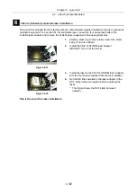
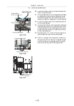
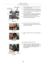
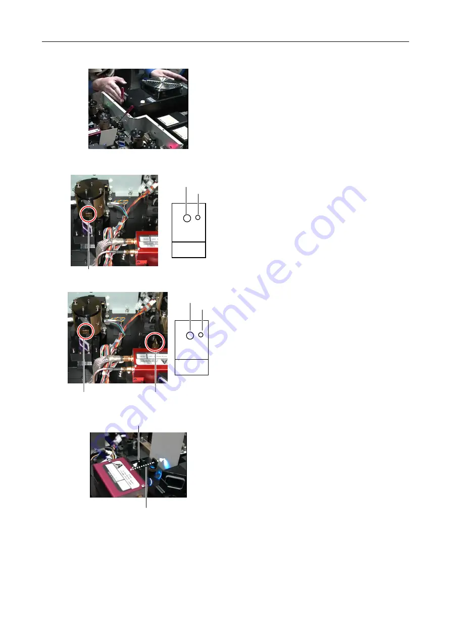
(2) Attach another centering tool to the laser module at
position B shown in the figure below. Adjust the
beam shift part with respect to the centering tool at
position A and move the laser body with respect to
the centering tool at position B so that the Ar laser
light roughly enters the hole L of each centering tool.
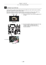
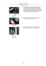
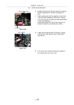
(3) Tighten the clamp screws of both the Ar laser body
fixing part and the Ar laser mirror adjustment part to
secure the respective parts.
Figure 5.4-50
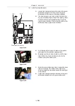
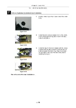
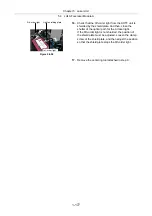
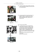
<for LU4> (Do not use in this system.)
Aim the 1st-order light of the laser at the hole of the
centering tool attached in step 3 by moving the Ar
laser body. The laser light must pass through the
hole.
Hole L
Hole S
A
Hole L
Hole S
A
Centering tool
B
Centering tool
1st-order light
0th-order light
Summary of Contents for Eclipse Ti Series
Page 2: ......
Page 14: ......
Page 256: ......
Page 258: ......
Page 260: ...Contents 2 2 8 2 Environmental Conditions 2 70 8 3 Safety Standards Compliance 2 71 ...


