JAA78851-R.3617.A
- L21・AF-S DX17-55/2.8G -
(GND)
(+)
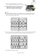
C H 1 = 2 0 m V C H 2 = 2 0 m V 5 m s / d i v
A C 1 0 : 1 A C 1 0 : 1
NORM 200KS/s
・
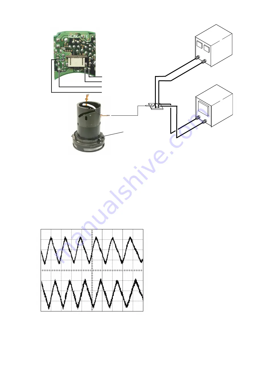
Connection diagram
Oscilloscope(2ch)
Oscilloscope(1ch)
Power )
Power supply(-)
Power supply
Set values
5.0V
100mA
Self made tool
Oscilloscope
(2ch)
CH1
CH2
Magnetic tape unit
Self made
tool
・
How to make an inspection and adjustment
①
Make sure that the current and voltage of the connected rated voltage power supply are set values.
Then, turn the power on.
②
Set the oscilloscope and turn the magnetic tape unit by hand.
Note
:
Because the shape of waveform varies according to the driving speed of magnetic tape unit, set
Time/Div accordingly.
③
In case of detecting any wide waveform noise, use the filter function.
How to set the filer function by Yokogawa-manufactured DL1540
1. Press the filter button.
2. Select "Smooth" in the menu on the PC screen.
●Setting of oscilloscope
V/Div
(
CH1
)
:
20 mV
V/Div
(
CH2
)
:
20 mV
Coupling
:
AC
Time/Div
:
5 m Sec
Trigger Mode
:
NORMAL
Trigger Coupling
:
AC
Trigger Source
:
CH1
Trigger Position
:+
4div
Trigger Type
:
EDGE
Trigger Level
:
0 V
INPUT (ch1)
:
AC
INPUT (ch2)
:
AC
Standard
:
The amplitude of every pulse/waveform should be 50mV or more.
Note
:
Check the waveform by letting the focus ring to travel from the infinity-end to the near
distance-end and vice versa.
INC


