background image

- 34 -

Appendix: Specifications

Film used:

35mm film (color/monochrome, negative/
positive)
Mounted slides (3.0mm or less and 1.1mm or
more in thickness)
Strip film (up to 6 images)

Scanning method:

Stepper-driven film stage, single pass method

Sensor:

2,592 pixel linear CCD image sensor

Light source:

RGB LED Array

Color separation:

RGB line sequential

Scanning area:

24.3 x 36.5mm, 2,592 x 3,888 pixels.
Strip film holder aperture is 23.4 x 35.4mm.

Scanning resolution:

Pixel size:

9.4 micron square pixel

Pixel density:

106 pixels/mm, 2,700 dpi (on film surface)

A/D conversion:

12 bits/color

Output data:

Full color (8 bits/color)

Focus:

Auto-focus

Film holder:

Not required for mounted slide scanning.
FH-2 is used for strip film scanning.

Interface:

SCSI-2 compliant

Size:

6.0 (W) x 10.5 (H) x 2.5 (D) inches
(151 x 267.5 x 63.3mm)

Weight:

Approx. 4.2lbs (1.9kg)

Power supply:

AC 100 - 120V/AC 200 - 240V, 50/60Hz,
0.80 - 0.4A

Temperature:

50˚F – 95˚F  (10˚C  – 35˚C)

Humidity:

20% – 85% (no condensation)

Options:

Nikon Auto Slide Feeder SF-100

Summary of Contents for LS-1000

Page 1: ...tions 2 4 Notes on Use 2 5 Cleaning the Unit 3 Parts Identification 3 1 Main Unit 3 2 Display LED 3 3 Strip Film Holder FH 2 4 Connecting the LS 1000 4 1 Before Connection 4 2 Connecting the Power Cord 4 3 Connecting the SCSI Cable 4 4 Setting the SCSI ID 5 Operation 5 1 Turning on the Power 5 2 Film Insertion 6 Troubleshooting Appendix Specifications Index ...

Page 2: ...nd Windows is a trademark of Microsoft Corporation IBM PC AT is a trademark of International Business Machines Corporation Other brand or product names are the trademarks or registered trademarks of their respective holders Indication The indications in this manual signify important safety precautions In order to use this product safely please read every section where these indications are placed ...

Page 3: ... Increase the separation between the equipment and receiver Connect the equipment into an outlet on a circuit different from that to which the receiver is connected Consult the dealer or an experienced radio TV technician for help CAUTIONS Modifications The FCC requires the user to be notified that any changes or modifications made to this device that are not expressly approved by Nikon Corporatio...

Page 4: ...ter and which is more than AWG18 in thickness At voltages of AC 125V or less use a power cord that complies with the safety standards of the country in which it is used which has a plug rated for AC 125V 10A and insulation of SVT type or better and which is more than AWG18 in thickness Be sure that the electrical outlet of the power supply is grounded Conduct the grounding in common to the other m...

Page 5: ...e power switch on On no account disassemble the Unit The high voltage parts inside the unit can cause electric shock Do not insert any foreign objects inside the unit If flammable objects metal or water come in contact with the interior of the unit failure fire and or an electrical shock may result Avoid harsh substances such as alcohol benzine thinner or pesticides as failure fire and or an elect...

Page 6: ...epresentative in your country Storage and Operating Locations Proper storage will ensure the long life of the Unit In order to avoid internal dust while being stored it is recommended that an appropriate cover be used on the Unit Do not store or use where The temperature is above 95 F 35 C or below 50 F 10 C the temperature changes drastically or condensation occurs The humidity exceeds 80 ...

Page 7: ... 7 The Unit is exposed to direct sunlight The atmosphere is excessively dusty The Unit may be subjected to excessive vibration or physical shocks ...

Page 8: ...ble surface for operation If operated in any other way problems will occur Transportation Precautions When transporting the Unit pack the unit with the original package box and packing material provided by Nikon WhenTaking the Unit Out ofThe Country The use of this product may violate local laws and restrictions in some countries If this is the case we cannot bear any responsibility for any violat...

Page 9: ... reproduction of stamps issued by the government and certified documents stipulated by law is prohibited Cautions on certain copies and reproductions The government has issued cautions on copies or reproductions of securities issued by private companies shares bills checks gift certificates etc commuter passes or coupon tickets except when a minimum of necessary copies are to be provided for busin...

Page 10: ...find this manual helpful 1 1 Features The LS 1000 is a film scanner capable of scanning 35mm film color monochrome negative positive at high speed and high resolution 3 color high brightness LED illuminant eliminating the need for illuminant maintenance High speed single pass scanning capability High quality images produced by using a 12 bit A D converter Maximum pixel count of 2 592 x 3 888 and h...

Page 11: ...elow for the amount of space to be provided If possible place a suitable cover over the unit to avoid dust accumulating when it is stored In the case of vertical installation In the case of horizontal installation 23 6inches 60cm 4inches 10cm 2 5cm 2 5cm 2inches 5cm 2inches 5cm 2inches 5cm 2inches 5cm 23 6inches 60cm 4inches 10cm ...

Page 12: ...nit 2 2 Accessories The following items are included with your LS 1000 When you open the package check whether all the items are present If there are any missing items please contact your retailer immediately LS 1000 Main Body 1 Power cord 1 The shape of the plug depends on the country of use SCSI cable 1 50pin full pitch Dsub 25pin FH 2 Strip Film Holder 1 Terminator 1 LS 1000 user s manual s Sof...

Page 13: ...r less than 1 1mm nor more than 3 0mm thick If the slide mount is not flat on its surface you may feel some roughness when mounting or unmounting the slide Don t force the slide mount or strip film holder into or out of the unit if it does not move smoothly When scanning a film don t touch or unmount the slide mount or strip film holder Keep the unit in a horizontal position ...

Page 14: ...leaning always turn the power off and pull out the power plug Since the front cover is made from plastic material remove dust with a blower or a dry cloth Use a soft dry cloth to remove dust from the metal panel at the rear If the unit has become badly soiled clean with a cloth moistened with a neutral liquid detergent then dry with a dry cloth Avoid harsh substances such as alcohol benzine thinne...

Page 15: ...ide autofeeder is connected to this option connector Status Display LED Shows the scanner status Power Switch Directly turns the AC power on off Ventilation Holes Since air is drawn in through these holes make sure that they are not blocked by other equipment Film Slot Option Connector Status display LED Power Switch Ventilation Holes ...

Page 16: ...CSI cable connection No difference between IN and OUT SCSI ID Switch Sets the SCSI ID number Numbers 0 to 7 are shown and valid AC Inlet Connect to the AC power source with the power cord provided 5 SCSI ID switch SCSI Connector AC Inlet ...

Page 17: ...ery 1 5 seconds Blinks slowly during operation BUSY status Also blinks when the power is switched on and during initialization Fast blinking about 5 times a second Blinks fast when an error occurs either in the LS 1000 or in communication ERROR status Note The blinking cycle may sometimes be irregular but this does not necessarily signify a product malfunction Status display LED ...

Page 18: ... This strip film holder can be used with a strip of film containing up to six images Lower holder Upper holder Lower holder concave section Film sits here Aperture Holder snap Holder snap Adaptor snap Aperture Adaptor cover Adaptor ...

Page 19: ...PC AT or compatible in which an SCSI board has not been installed install an SCSI board as explained in the manual supplied with the board When installing an SCSI board for the first time be careful not to use the same number as used for another purpose such as an I O address interrupt number or graphic board DMA channel Note Make sure that the PC is powered off before installing the SCSI board ...

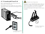
Page 20: ...urce noise interference Do not extend the power cord of the product as this may cause malfunction The shape of the plug depends on the country of use 4 2 Connecting the Power Cord Before connecting the power cord confirm that the unit s power switch is in the off position Insert the female end of the supplied power cord into the AC inlet located on the rear panel then insert the plug into the AC p...

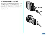
Page 21: ...t all SCSI devices including the computer system have been turned off Connect the unit to the computer using the SCSI cable After attaching the connector be sure to lock it in place You can connect the SCSI cable to either of the SCSI connectors on the rear panel of the unit 5 5 ...

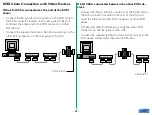
Page 22: ...SCSI devices 5 When SCSI devices are connected connect them so as not to make a loop and attach terminators to both ends of the SCSI chain Since the terminator is built into the host computer in most cases the host computer should be at the end of the SCSI chain The operation manuals of some notebook computers require a terminator to be attached outside the computer please refer to the operation m...

Page 23: ...l resistance to the other SCSI connector on the rear panel of the Unit If LS 1000 is connected between the other SCSI de vices Connect the 50 pin full pitch connector of the SCSI cable to the SCSI connector located on the rear of the Unit and insert the other end to the SCSI connector of other SCSI device Connect the other SCSI device by using the other SCSI connector on the rear panel of the Unit...

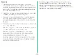
Page 24: ...Terminators must be attached to the devices located at both ends of the SCSI chain If the host computer is a Macintosh the Macintosh itself will provide termination at one end of the chain If the host computer is an IBM PC AT or compatible equipped with an SCSI board the SCSI board itself will present termination at one end of the chain Note that when an SCSI chain connection is made inside a comp...

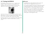
Page 25: ...u must change the ID number of the other SCSI device or the ID of the LS 1000 to avoid any conflict Remarks To change the ID confirm that the LS 1000 power is off The ID cannot be changed when the power is on As 7 has been assigned for the CPU and 0 has been assigned to the built in hard disk for a Macintosh and 0 and 7 have also been assigned to other personal computer systems any number from 1 t...

Page 26: ...egin to blink to indicate scanner initialization POWER ON Remarks To turn the LS 1000 power off turn the host computer off first the other SCSI devices next and the LS 1000 last reverse order from switching on Once the power is turned off please wait five seconds or more before turning the power on again Do not turn the power on off while the scanner is scanning ...

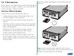
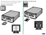
Page 27: ...unted slide so that the emulsion surface is facing toward the right shiny surface facing left When the LS 1000 is installed horizontally insert the mounted slide so that the emulsion surface is facing downward shiny surface facing upward All film has an emulsion surface and a base surface The emulsion surface is slightly convex and concave The base surface is neither concave nor convex and is shin...

Page 28: ...d orientation of a mounted portrait or landscape slide is shown below If the top and bottom are reversed modification is possible by using the software Orientation of a portrait slide Orientation of a landscape slide ...

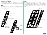
Page 29: ...ikon printed on the adaptor cover of the upper holder is facing upward Step 2 Place the strip film on the concave section which is fixed in the adaptor of the lower holder Be sure to place the strip film so that the emulsion surface will be facing down the shiny surface will be facing up The direction is correct if the image number can be read Adaptor snap Upper holder Adaptor cover Insertion dire...

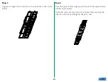
Page 30: ... film with an aperture in the lower holder Step 4 Close the upper holder aligning both ends of the upper holder and the lower holder Fasten the snaps at both ends of the holder after securing the adaptor cover and fastening the adaptor s snap ...

Page 31: ... aperture through which the image is to be read toward the slot The film holder can be inserted into the LS 1000 from either end Decide the insertion direction of the film holder according to which image is to be read The first image will be read The second image will be read The third image will be read The sixth image will be read The fifth image will be read The fourth image will be read ...

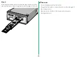
Page 32: ...he unit and the mark comes in alignment with the edge of film slot Remarks Do not forcefully insert the film holder Though the film holder is made of plastic it will be damaged if film is forced into it Remove dust on the film or film holder with a blower or photographic brush ...

Page 33: ...r recommended system requirements Provide the recommended system Have you installed software For information on installing and operating software refer to the software manual provided with the unit Have you properly set the configuration such as CONFIG SYS If you have installed applications for Windows for instance note that the configuration may change automatically For Windows version Poor image...

Page 34: ...trip film holder aperture is 23 4 x 35 4mm Scanning resolution Pixel size 9 4 micron square pixel Pixel density 106 pixels mm 2 700 dpi on film surface A D conversion 12 bits color Output data Full color 8 bits color Focus Auto focus Film holder Not required for mounted slide scanning FH 2 is used for strip film scanning Interface SCSI 2 compliant Size 6 0 W x 10 5 H x 2 5 D inches 151 x 267 5 x 6...

Page 35: ...1 vertical 11 L LED See Status display LED M Main unit 15 16 Maintenance 14 O Operating environment 11 Option connector 15 P Power cord connecting 20 Power switch 15 S SCSI cable 12 21 22 SCSI connector 16 SCSI ID 25 SCSI ID switch 16 SF 100 auto slide feeder 13 Slides mounted inserting 27 28 orientation of landscape slides 28 orientation of portrait slides 28 Specifications 34 Status display LED ...

Page 36: ...ration Adresse du fabricant Fuji Bldg 2 3 Marunouchi 3 chome Chiyoda ku Tokyo 100 Japan est conforme aux normes suivantes EN55022 Classe B EN50082 1 IEC801 2 1991 4kV IEC801 3 1984 3V m IEC801 4 1988 1kV AC 0 5kV I O selon les dispositions de la directive de la CEE 89 336 EEC ERKLÄRUNG ÜBER EG NORMENGERECHTHEIT Wir Name Nikon UK Limited Anschrift Nikon House 380 Richmond Road Kingston Surrey KT2 5...

Reviews: