4
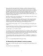
A) take out any transport screws from bottom of case and throat of slide carrier, where example
MA-20 slide mount adapter fits into. Store them by screwing them in the back panel, threaded
holes are just above the SCSI connectors.
B) take off 4 screws on back panel, separate halves of metal case, and set aside, put in vial #1.
Check to see if there is any corrosion, water damage, or any evidence of liquid spillage inside.
Check to see if there are any loose parts inside, screws, plastic bits, packing materials, etc
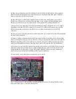
c) loosen 4 screws on right side of circuit board which have large rectangular 1/4" x 1/2" square
grounding solder pads. Do NOT remove 2 screws with 1/4" square solder pads as they hold the
SCSI controls subassy; also leave the other 4 screws on the circuit board next to the SCSI
connectors.
D) remove 4 screws on back panel next to SCSI connectors, put in vial #2. The circuit board should
be loose but still attached.
E) remove 5 cables on bottom side of circuit board and 2 cables on top side of circuit board. May
need to use fingernail, thin jewelers screwdriver or forcep to separate the cable jack and connector.
Refrain from pulling on the wires with fingers or forcep; just get it to barely separate, then insert
and twist a flat bladed screwdriver in the gap. Don't need to label them as they are all different.
Lube connectors, especially the metal wiring inserts in the connector with Teflon. The connectors
depend on spring-loaded wiring inserts to make reliable pressure contact with the jack pins. The
spring-loaded inserts often micro-corrode due to high humidity, as these are only commercial
spec'd connectors (not like high-reliability military spec'd connectors)
F) remove the 4 screws that hold in circuit board, put in vial #3
Fig 2. Circuit board, see mid-board the vertical long black connector for orange flexible circuit,
note on the right-edge is a vertically sliding latch


