5
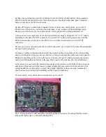
G) from the top, locate orange flexible ribbon cable and lift the left-edge locking mechanism
delicately with a flat bladed screwdriver. Remove the flex ribbon cable and lube contacts and the
jack’s locking mechanism with Teflon.
H) separate circuit board from mechanism handling by the edges, inspect for dirt, corrosion, for any
scratches or cracked board, and sniff for any burned part(s). Store in anti-static bag and set aside.
I) inspect power supply in left side, especially for any bloated or leaking round cylindrical brown
capacitors; 4 larger ones, 3 black striped smaller ones. There is a soldered-in ceramic 3.15A
internal fuse F1. Disassemble, unsolder and replace if needed
J) remove front plastic bezel, there are top and bottom plastic snaps
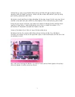
K) lubricate the three X-axis rails with Teflon with several drops of lube. Use a flat bladed
screwdriver and surface tension of the liquid lube to place it and tilt mechanism until the entire rails
are uniformly covered.
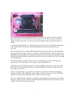
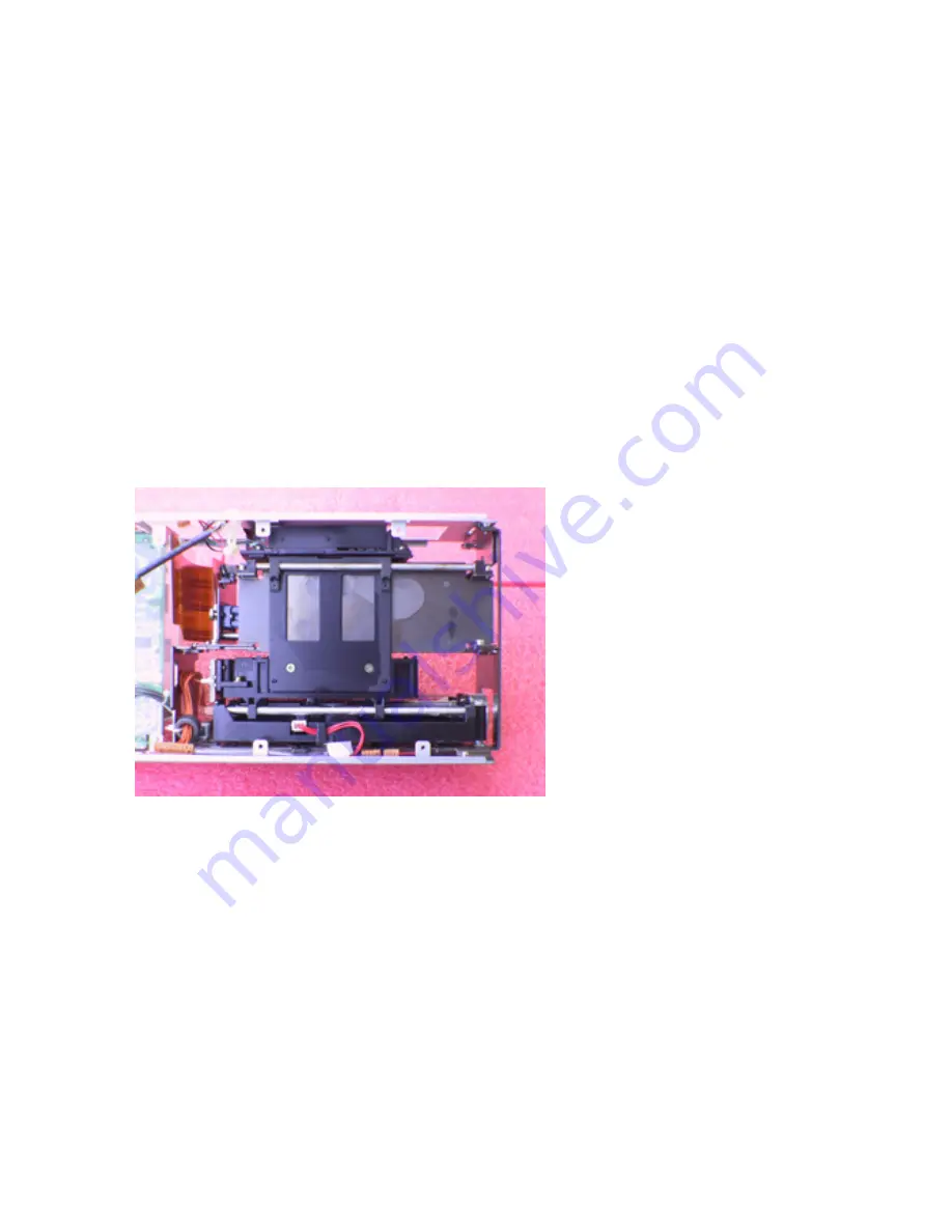
Fig 3. Left side of scanning mechanism, two of three X-axis rails and forked guides of Autofocus
Z-axis mechanism is visible, under circuit board


