background image

Summary of Contents for SB-102 os

Page 1: ...Nikon NIKONOS Speedlighf INSTRUCTION MANUAL ...

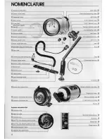
Page 2: ...ckle lock release latch calculation dial screw Exposure calculation dial Exposure calculation dial Distance scale scale Distance lines Non TTL auto shooting aperture scale Non TTL auto shooting aperture index scale 2 Joint collar Flash head positioning index Joint plate i ion mark i ion mark I Joint Arm Grip O rings and lubricant Arm knob Battery chamber cap index Target light holder mode selector...

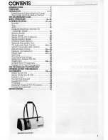
Page 3: ...lation Dial 22 TTL Automatic Flash Control 22 23 Non TTL Automatic Flash Control 24 Manual Flash Control 25 26 Exposure Compensation 26 27 Ready Light 27 28 Test Firing 28 Cord Fastening Hanger 29 Wide Flash Adapter SW 102 29 Target Light 29 30 Multiple Flash Photography 30 Daylight Fill In Flash Photography 30 TIPS ON SPEEDLIGHT PHOTOGRAPHY 31 OPTIMUM BATTERY PERFORMANCE 32 ACCESSORIES 33 34 Sens...

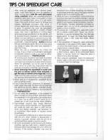
Page 4: ..._______ STOP READ THIS NOTICE BEFORE USING YOUR SB 102 THE O RING SEALS MUST BE EXAMINED AND LUBRICATED BEFORE USE TO AVOID DAMAGING THE SPEEDLIGHT This Nikonos 8peedlight 88 102 uses O rings to seal and waterproof the junctions between parts Your Nikonos 8peedlight 88 102 should not be considered waterproof until you have examined the user service able O rings one each for the battery chamber cap...

Page 5: ...ilar object to apply the lubri cant small hairs may fall into the channel and allow water to enter the flash unit While lubricating each O ring examine it with your fingertips for imperfec Fig 3 tions If an O ring is properly lubricated it will glisten and will not have gobs of lubricant on it To ensure the longest possible flash unit life apply lubricant whenever necessary Lubrication protects th...

Page 6: ...rom authorized Nikon dealers and service centers The O rings and their sealing method The method used by the O rings to seal and waterproof the flash unit is shown in the following illustrations When a low level of pressure exists for instance just under the water s surface each O ring seals its groove by its own elastic force see Chart A When the pres sure increases at greater depths the O ring s...

Page 7: ...he procedures in PREPARATION 5 Do not allow the speedlight to be exposed to direct sunlight for long periods And never place the speedlight in an area where the temperature is or may rise to 60 C 140 F such as in a closed car or car trunk during w arm weather 6 High voltage circuitry may cause electrical shock if water enters the flash unit Should water get inside the flash unit take it with the b...

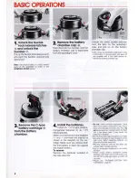
Page 8: ...talled in the side slots fi rst Unlock the silver buckle catches from the pins on the speedlight case and pull up on the battery chamber cap After using the speedfight underwater rinse it thoroughly in running water and wipe off any droplets with a soft cloth before re moving the battery chamber cap Do not Insert batteries improperly leave flash unit turned on when not in use Any of these may dama...

Page 9: ...ce the battery chamber cap Check the O ring Before replacing the battery chamber cap examine its O ring for dust and scratches and be sure it is properly seated and lubricated 9 Loosen the joint knob To loosen the joint knob turn it counterclockwise while holding the joint plate 7 lock the buckles Push the battery chamber cap against the speedlight case so it is fully seated hook the silver buckle...

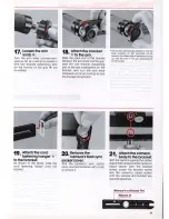
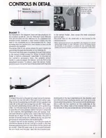
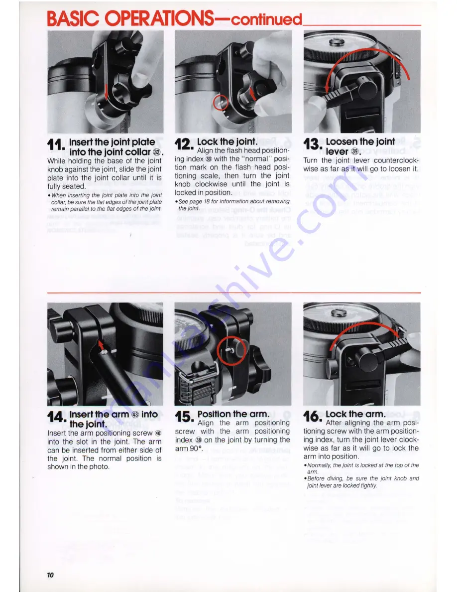
Page 10: ...joint Align the flash head position ing index with the normal posi tion mark on the flash head posi tioning scale then turn the joint knob clockwise until the joint is locked in position oSee page 18 for information about removing the joint 15 Position the arm Align the arm positioning screw with the arm positioning index on the joint by turning the arm 90 13 Loosen the joint lever Turn the jOint ...

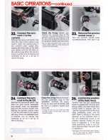
Page 11: ...n the arm knob clockwise as far as it will go to lock the bracket into position 20 Remove the camera s flash sync socket cover Turn the camera s sync socket cover counterclockwise with a coin to remove it The correct arm bracket position is with the three washers on the underside of the bracket the rubber side of the bracket facing up and flat side of the grip perpendicular to the bracket 21 Attac...

Page 12: ...nd lubricated o Do not apply excessive force to the sync cord s camera plug and avoid twisting the cord as much as possible Check the a ring Before connect ing the speedlight plug to the speedlight examine the plug s O ring for dust and scratches and be sure it is properly seated and lubricated To keep the sync cord out of the way while shooting attach it to the hook of the cord fastening hanger 2...

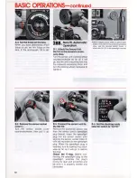
Page 13: ...A steps are for TTL automatic opera tion with the Nikonos Vcamera the 8 steps are for non TTL automatic operation with the Nikonos V Nikonos V A or III the optional Sensor Unit SU 101 is required for non TTL automatic operation For information about manual flash operation see pages 25 to 26 500 j 640 1000 j 1250 28A TTL Aut matic Operation A 1 Set the shooting mode selector switch to TTL 27 Set th...

Page 14: ...B 3 Connect the sensor cord to theSB 102 Remove the dust proof plastic cap from the sensor cord s speedlight plug black Insert the speedlight plug into the sensor socket after aligning the sensor socket index with the red index on the speedlight plug When the speedlight plug is inserted turn its locking ring clock wise as far as it will go to secure the plug Check the O ring Before con necting the...

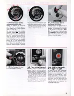
Page 15: ...e Nikonos V the shutter speed LED indicator inside the viewfinder will blink if the shutter speed mode selector dial is set at A or at any shutter speed from 1 1000 to 1 30sec As soon as you turn on the S8 102 when using the Nikonos IV A the viewfinder LED turns off o For normal shooting the T S switch should be in the OFF position For information about the T S switCh see pages 29 to 30 B 6 Set th...

Page 16: ... turn the power switch on the speedlight to OFF Turning the pcwer switch off between ses sions will also help prevent battery leakage 16 31 Take the picture When the shutter is re leased the speedlight fires After you take the picture watch either the ready light inside the camera s viewfinder or the one on the 88 102 After a few seconds it will light again to indicate tile flash unit is fully rec...

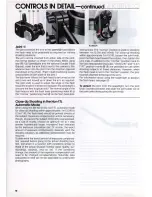
Page 17: ...er clockwise as far as it will go to lock the arm into position When the arm is attached in this manner the speedlight s axis will always inter sect with the lens s optical axis even if the flash head is moved up or down on the arm Normally the joint is locked at the top of the arm Before diving be sure the jOint knob and jOint lever are locked tightly To attach the arm to the bracket turn the arm...

Page 18: ...humb choose an aperture 1 2 to 1 step smaller numerically larger f numbers than indicated by the exposure calculation dial Of course the exact amount of exposure compensation depends upon the shooting situation so additional compensation may be required To determine the exact amount of exposure compensa tion required before going to the actual shooting loca tion test shoot in a location with condi...

Page 19: ...the red index on the speedlight plug When the speedlight plug is inserted turn its lock ing ring clockwise as far as it will go to secure the plug Never submerge the speedlight in water with the sensor socket cover removed or get the sensor cord plugs wet Always make sure either the sensor socket cover or the sensor cord plugs are securely attached before entering the water After shooting underwat...

Page 20: ... sensor unit must be set according to the instructions in Step B 6 page 15 To obtain the correct exposure position the sensor as close to the lens as possible For more information about non TTL automatic operation see page 24 Synchronization Speed The shutter speed at which the S8 102 synchronizes with a camera depends upon the camera being used The table shows the flash sync speeds of various cam...

Page 21: ...apertures is larger trom f 2 8 to f 22 when using ASAIISO 100 film than with non TTL flash you can shoot at a variety of flash to subject distances The farther the subject the more light emitted by the flash unit the closer the subject the less light given off In addition the TTL mode makes daylight fill in flash and close up photography easier than ever The useable film speed range for TTL operat...

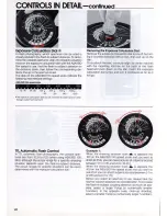
Page 22: ...anges for specific situations can be easily determined with the exposure calculation dial 22 Removing the Exposure Calculation Dial Remove the exposure calculation dial screw by turn ing it counterclockwise with a coin then pull up on the dial To re attach the dial correctly align its center notches with the mounting notches on the back of the flash head and push down on the dial Insert the exposu...

Page 23: ...le select f 2 S In the TTL automatic mode the S8 102 s useable ASAIISO film speed range is from ASAIISO 25 to 400 its useable aperture range is from f 2 B to f 22 and its flash to subject coupling distance range is from O 3m 1 ft to 22 m 72 2ft However the relationship between the useable aperture range and the flash to subject coupling distance range varies according to the ASAIISO speed of the f...

Page 24: ...ration the minimum flash to subject coupling distance is always a 6m 2ft The maximum flash to subject coupling distance is determined by your choice of shooting situation marks regardless of the ASAIISO speed of the film in use The coupling ranges that correspond to the four shooting situation marks are shown in the chart 24 Example When shooting underwater while using ASA ISO 100 film the useable...

Page 25: ... When shooting a subject underwater at 1m 3 3 ft with out using the wide flash adapter while using ASAIISO 100 film you can select one of three aperture mode settings f 16 at MFULL flS at M1 4 or f 4 at M1 16 If the shooting distance changes to 5m 16 4 ft but you still want to use MFULL you should use an inter mediate aperture setting between f 2 Sand f 4 To determine the correct f stop without us...

Page 26: ...art The useable aperture range for TTL automatic flash photography changes according to the exposure com pensation value being used Before using the exposure calculation dial to determine the useable aperture range align the correct shooting situation mark with new compensation setting on the ASAIISO film speed scale 26 Exposure Compensation When the Nikonos V is used with the SB 102 in the TTL or...

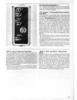
Page 27: ...lways confirm that the viewfinder ready light is lighted before shooting o When the shutter speed mode selector dial or shutter speed dial of the Nikonos Vor Nikonos IV A is set at M90 or M the viewfinder ready light lights when the flash unit s ready light lights Ready Light After its power switch is turned on the ready light on the 8B 102 will light to indicate that the 8B 102 has re cycled and ...

Page 28: ...the shutter speed shooting mode is improperly set When the camera is set at M90 or M the camera s exposure meter will not operate even if the shutter release button is depressed Test Firing To determine whether or not the flash illumination is sufficient for a correct exposure especially when using the non TTL automatic mode with distant subjects or when using bounce flash photography test fire th...

Page 29: ...en setting the exposure calculation dial o To prevent overexposure during close up shooting within approximately O 6m 2ft attach the adapter even if using a lens other than the UW Nikkor 15mm fI2 BN o To prevent the loss of the SW 102 and to enable it to be attached quickly tie one end of a piece of string to its hole and tie the other end to the speedlight Target Light Function The S8 102 s targe...

Page 30: ...For multiple flash operation as shown in the diagram use either an S8 102 or S8 101 as the master flash unit the speedlight connected to the camera Set the T S switch of the slave flash unit the speedlight not con nected to the camera to SLAVE or T S After confirming that the flash units ready lights are lighted release the shutter to fire the master flash unit At the same time the slave unit will...

Page 31: ...ached to the Nikonos IV A certain optical finder models for older UW Nikkor 15mm fl2 B lenses cannot be attached If this presents a problem for you authorized Nikon dealers and service centers can perform the necessary modifications 4 One of the benefits of using a speedlight under water is that it restores natural colors to subjects by removing the water s bluish cast Occasionally though you may ...

Page 32: ...rsal of the positive and negative terminals will result in leakage If leakage should occur clean the SB 102 carefully or take it to an authorized Nikon dealer or service center The SB 102 requires an excessive current so the life span of the batteries may be shorter than other speedlights 8 NiCd batteries In comparison with regular batteries NiCd bat teries provide faster recycling and higher effi...

Page 33: ...ed on the camera s accessory shoe the sensor holder enables the Sensor Unit SU 101 to be mounted on the bracket Double Flash Bracket This accessory allows two flash units to be mounted on the camera at one time thereby doubling the amount of flash illumination available This bracket is especially useful during close up shooting because it enables the subject to be evenly illuminated from the left ...

Page 34: ...AIISO film speed scale at its original setting and turn off the speedlight which is attached to the gray sync cord Should you turn off the speedlight which is attached to the black cord TTL automatic flash control is automatically canceled and the unit will fire at its maximum output regardless of the setting Non TTL automatic flash exposure is not possible when using two speedlights connected by ...

Page 35: ...hours at room temperature More flashes and shorter recycling times in the TTL non TTL M1 4 and M1 16 modes TTL ASAIISO film speed coupling range ASAIISO 25 to 400 useable aperture range f 2 8 to f 22 at ASAIISO 100 coupling distance range 0 3m 1ft to 11 m 36 1ft at ASAIISO 100 on land 0 3m 1 ft to 5 6m 184ft at ASAIISO 100 underwater Non TTL Useable apertures f 4 and f 8 at ASAIISO 100 coupling di...

Page 36: ...n any form of this manual in whole or in part except for brief quotation in critical articles or reviews may be made without written authoriza tion from the publishers N lro NIPPON KOGAKU K K Printed in Japan 8 067 A06 ...

Reviews: