Chapter 5
Assembling
96
4
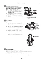
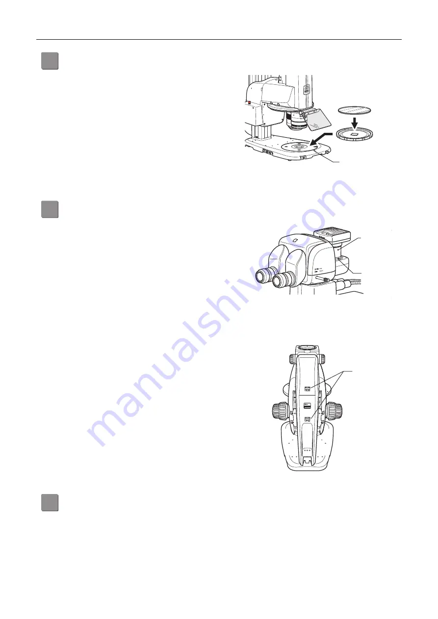
Attach the C-SSL DIA Sliding Stage.
Attach the C-SSL DIA Sliding Stage to the P2-PB Plain
Base, P2-DBL LED Diascopic Illumination Base or
P2-DBF Fiber Diascopic Illumination Base.
(1) Loosen the M4 set screw for the stage plate on the
base using a hex driver (nominal designation: 2) to
detach the stage plate.
(2) Fit the sliding stage into the base and tighten the
stage plate fixing screw.
(3) Place the stage plate detached in Step (1) on the
sliding stage.
Attaching the DIA sliding stage
by tightening the screw
5
Attach a Camera.
(1) Screw the C-mount lens in the DS camera head,
attach it to the LV-TV TV Tube Adapter, and then
tighten the camera attachment direction fixing screw
on the TV tube adapter.
(2) Loosen the TV tube adapter fixing screw located on
the mount on the tube side, attach the TV tube
adapter, determine the DS camera head orientation,
and then tighten the TV tube adapter fixing screw.
(3) Connect the camera cable connector of the DS
camera head to the connector “CAMERA” of the
DS-L3/DS-U3 DS camera control unit using a
dedicated camera cable.
Attaching the camera by tightening the screws
Use two camera cable clips that are located on the
rear side of the focus unit.
P2-FU
M A D E I N C H I N A
M A D E I N C H I N A
Camera cable clip
6
Attach other devices.
Devices such as those listed below can also be attached.
For details on assembly, see the instruction manual supplied individually with the devices.
C-TRS Tilting Stage: Attached to the base or stand
P-DF LED Dark Field Unit: Attached to the base, stand or C-SSL DIA Sliding Stage
P2-FIRL LED Ring Illumination Unit: Attached to the outer cylinder of the objective
Camera cable
clip
Fixing screw
Camera
attachment
direction
fixing screw
TV tube
adapter
fixing screw
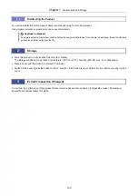
Summary of Contents for SMZ18
Page 1: ... M608EN01 Research Stereo Microscope SMZ25 SMZ18 Instruction Manual M608 E 13 5 NF 1 ...
Page 2: ......
Page 20: ...Chapter 1 Components 6 ...
Page 32: ...Chapter 2 Microscopy Procedures 18 ...
Page 84: ...Chapter 4 Functions and Operations of the Devices 70 ...
Page 114: ...Chapter 6 Troubleshooting 100 ...
Page 118: ...Chapter 7 Maintenance and Storage 104 ...
Page 119: ...105 Chapter 8 Specifications ...


