VRA51701-R.3607.A
-
A11
・
-
LS-9000
①
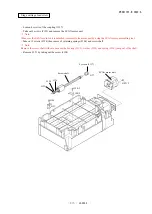
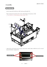
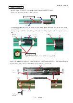
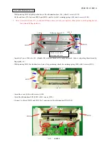
With the SCAN motor assembly tool (J61192), attach the SCAN motor (#509) to the motor base plate (#138) with 2
screws (#192).
Procedure for mounting SCAN motor unit
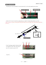
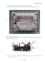
②
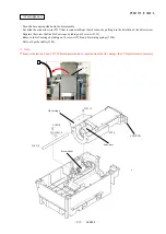
With the SCAN motor adjustment tool (J61193), fit the coupling (#137) in it and tighten the tool screw by the Hexagonal
wrench 1.5mm (J92122).
To fit #137 in the tool, put
the surface without engraved
letters to face side.
J61193
③
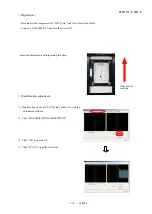
Attach the coupling that is set in the tool to the screw shaft.
④
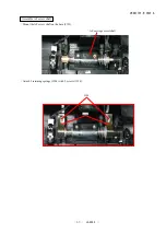
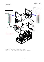
Attach the SCAN motor unit temporarily with 2 screws. Then turn the tool (J61193) slightly to find the position where
the shaft on the scan motor side does not turn. At this position, tighten 2 screws of the SCAN motor unit.
⑤
With the tool
(
J61193) being attached on #104, tighten equally 2 screws (#137) on the scan motor side.
⑥
Remove the tool (J61193).
⑦
Tighten equally 2 screws (#137) on the screw shaft side.
#137
#509
#192×2
#138
J61192
Tool screw
Turn slightly.
J61193
#104
Screw on the scan motor side
Screw on the screw shaft side
Screw shaft
Scan motor
Summary of Contents for Super Coolscan 9000 ED
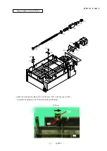
Page 25: ...VRA51701 R 3607 A A12 LS 9000 Stage carriage unit Place wires in position ...
Page 64: ...VRA51701 R 3607 A E1 LS 9000 ブロック図 BLOCK DIAGRAM ...
Page 74: ... ...
Page 75: ...A ...
Page 76: ... ...
Page 77: ... ...
Page 78: ... ...
Page 79: ...G F 2 0 ...
Page 80: ... ...
Page 81: ... ...
Page 82: ... ...

