VRA51701-R.3607.A
-
A16
・
-
LS-9000
#192×2
・
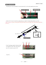
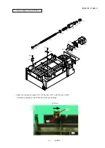
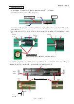
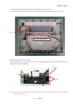
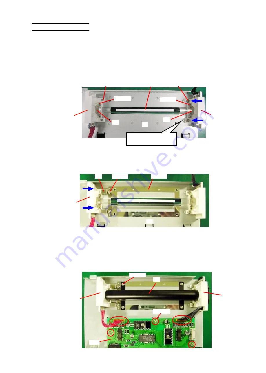
While pressing #B518 slightly on the boss of the illumination base (#61), attach 2 screws (#192).
・
Put the rod lens (#71) between #B518 and #B519, and fix it with 2 retaining springs (#68) and 4 screws (#184).
*
Note: Place the rod lens (#71) so that the diffusion sheet on it turns just upward. Wear gloves to avoid getting the rod
lens stained by fingerprint, etc.
#B519
Attach screws while
pressing on the boss.
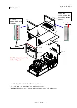
Assemble Illumination unit
・
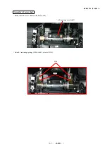
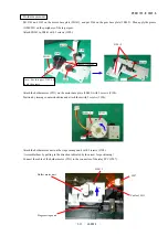
Assemble 2 pcs. of #64 into #61. (Handle #64 with care because it is easily deformed. Also avoid getting them stained by
fingerprint, etc.
)
・
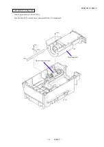
While pressing #B519 in the direction of arrow for positioning, attach the retaining spring (#69) with 2 screws (#192).
・
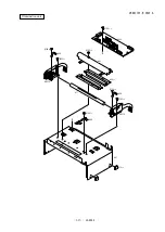
Attach the cover (#63) with 4 screws (#190).
・
Attach the illumination-PCB (#545) with 3 screws (#192).
・
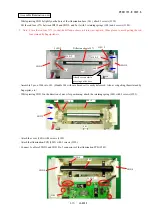
Connect 2 cables of #B519 and #B518 to 2 connectors of the illumination PCB (#545).
#63
#192×3
#545
#190×4
#184×2
#68
Diffusion sheet of #71
#68
#B518
#184×2
#61
#190×2
#69
#64×2
#61
#192×2
#B519
#B519
#B518
Summary of Contents for Super Coolscan 9000 ED
Page 25: ...VRA51701 R 3607 A A12 LS 9000 Stage carriage unit Place wires in position ...
Page 64: ...VRA51701 R 3607 A E1 LS 9000 ブロック図 BLOCK DIAGRAM ...
Page 74: ... ...
Page 75: ...A ...
Page 76: ... ...
Page 77: ... ...
Page 78: ... ...
Page 79: ...G F 2 0 ...
Page 80: ... ...
Page 81: ... ...
Page 82: ... ...

