VRA51701-R.3607.A
-
A18
・
-
LS-9000
B
#560
A
AB
S
#50
#522
#197
#192
x4
A
B
#35
#541
#192
x6
#45
#43
#42
#516
#551
#192
x4
#517
#510
#509
・
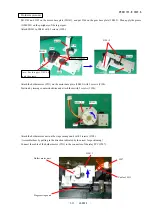
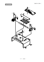
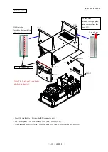
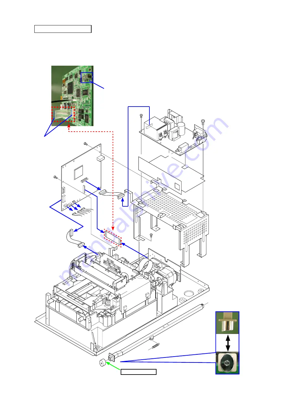
Attach the power base (#35) with 4 screws (#192).
・
Attach the insulating sheet (#50) and the power PCB (#522) with 4 screws (#192) and #197.
・
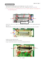
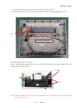
Connect each connector (#560, #509, #510, #517, #516, and #551), and attach the main PCB (#541) with 6 screws (#192).
・
Attach the power SW (#42) and hook the spring (#45).
Main PCB / Power unit
Adhesive: Super X
*
Note: Light blue side (cf. backside is white) for contacts of
#
551 should face the
IEEE connector.
#551
IEEE connector
Light blue side
Summary of Contents for Super Coolscan 9000 ED
Page 25: ...VRA51701 R 3607 A A12 LS 9000 Stage carriage unit Place wires in position ...
Page 64: ...VRA51701 R 3607 A E1 LS 9000 ブロック図 BLOCK DIAGRAM ...
Page 74: ... ...
Page 75: ...A ...
Page 76: ... ...
Page 77: ... ...
Page 78: ... ...
Page 79: ...G F 2 0 ...
Page 80: ... ...
Page 81: ... ...
Page 82: ... ...


