VRA51701-R.3607.A
-
A22
・
-
LS-9000
External view
・
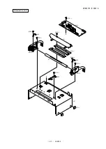
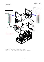
Insert the shield plate (#46) into the IEEE connector part.
・
Fix the rear panel (#32) with 3 screws (#192) and 2 screws (#188).
・
Attach the side cover (#31) with 8 screws at back (#192) and 10 screws at the bottom (#192).
#188×2
ICE
ABS
#31
#192
x8
#192
x4
#32
#36×2
#192
x10
#46
#192
x3
#36 Front side
Attach by aligning the line
of front panel.
Front panel's line
#36 Back side
Attach by leaving approx.
8-mm clearance from the
edge of #31.
Approx. 8 mm
#36×2
#192×8
#31
#192×10
#46
#32
#188×2
#192×3
#192×4
Note: The front panel was already
attached on Page A21.
Summary of Contents for Super Coolscan 9000 ED
Page 25: ...VRA51701 R 3607 A A12 LS 9000 Stage carriage unit Place wires in position ...
Page 64: ...VRA51701 R 3607 A E1 LS 9000 ブロック図 BLOCK DIAGRAM ...
Page 74: ... ...
Page 75: ...A ...
Page 76: ... ...
Page 77: ... ...
Page 78: ... ...
Page 79: ...G F 2 0 ...
Page 80: ... ...
Page 81: ... ...
Page 82: ... ...


