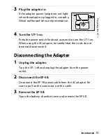
12
P
reparing the UT-1
Introduction
Connecting the Adapter
1
Insert the power connector.
Open the UT-1 battery-chamber (
qw
)
and power connector (
e
) covers and
then insert the EP-5B power connector in
the orientation shown (
r
). Position the
power connector so that it passes
through the power connector slot (
t
)
and close the battery-chamber cover.
2
Connect the AC adapter.
Connect the AC adapter power cable to the AC socket on AC
adapter (
q
) and the EP-5B power cable to the DC socket (
w
).
Summary of Contents for UT-1
Page 1: ...Communication Unit User s Manual En ...
Page 30: ...18 Installing the Wireless Transmitter Utility Introduction ...
Page 41: ...Copying Network Profiles to the Camera Using the UT 1 with a Computer 29 ...
Page 60: ...PC Mode Using the UT 1 with a Computer 48 ...
Page 69: ...57 Copying Network Profiles to the Camera Uploading Pictures to an ftp Server ...
Page 82: ...70 Uploading Images Uploading Pictures to an ftp Server ...
Page 103: ...Print Menu Guide 91 Print PrintModeOnly The UT 1 does not support this option ...
Page 106: ...Device Settings Menu Guide 94 ...
Page 138: ...126 ...
Page 139: ......


