background image

Summary of Contents for Cynema Soundfield CSF48A

Page 1: ...CYNEMA SOUNDFIELD SOUNDBAR SYSTEM BLENDING HIGH FIDELITY AND ARCHITECTURE ...

Page 2: ...lation and operation you will experience years of high performance trouble free use For information on the complete line of innovative Niles products please visit us at www nilesaudio com TABLE OF CONTENTS INTRODUCTION 4 FEATURES AND BENEFITS 5 SPECIFICATIONS 6 PARTS GUIDE 7 INSTALLATION CONSIDERATIONS 9 INSTALLING THE SYSTEM 15 SYSTEM APPLICATIONS 24 OPERATION POWERED SYSTEMS 28 OPERATION PASSIVE...

Page 3: ...acle 17 The power supply cord sometimes referred to as the Mains Plug is used as the disconnect device and shall remain accessible and operable at all times 18 Do not expose batteries to excessive heat such as sunshine fire or the like 19 Open flame sources such as lighted candles should NOT be placed on the apparatus WARNING To reduce the risk of fire or electric shock do not expose this apparatu...

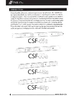
Page 4: ...cally the Cynema Soundfield s virtually flat appearance complements the latest flat panel displays perfectly Its unique in wall mounting system dramatically improves the ease of installation and contributes to dynamic audio reproduction Thin flat panel televisions must use thin speakers Thin speakers fall short of our standards for high fidelity Niles Cynema Soundfield is the solution that brings ...

Page 5: ...ing studs with ease NO HIGH VOLTAGE WIRING IN THE WALL DC power supply mounted separately sends low voltage DC power through wall to amplifier module allowing for wiring without the need for an electrician OPTIMAL SPEAKER PLACEMENT Mounting System allows for ideal placement of LCR speakers in any existing stud configuration SEAMLESS SIMPLE OPERATION FOR END USER System s Amplifier Module can learn...

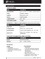
Page 6: ... 70dB or better Signal to Noise 1OOHz to 20kHz un weighted 75dB or better based on Rated Power POWER SUPPLY FOR MODELS CSF48A CSF55A AND CSF65A SPEC DESCRIPTION AC Input DC Output BOX CONTENTS All Models 3 Speaker Modules 1 In Wall Mounting System with Grille 100 240V 2 5A 50 60Hz 24V 5A Max 120W Max Powered Models Only 1 Amplifier Module 1 Cutout Template for In Wall Mounting System 1 Warranty Ca...

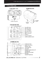
Page 7: ...tor L 1 Master Volume Control Master Power Switch ____ Audio Mute _ c J c J 1 J AMPLIFIER REAR VIEW Remote Control Sensor r tt UC R Channel Balance Control UC R Speaker Output Amplifier Power 24V DC Subwoofer Output Toslink Optical Input r 1 Stereo Input L Hanging Bracket __ Subwoofer Transmitter Power 0 5V H Aux Stereo Input r ttt t HDMI Output Pass through ______ HDMIInput rr 1 External IR Recei...

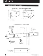
Page 8: ...er Cord 100 240V AC 50 60Hz 24V DC Power Cable IN WALL MOUNTING SYSTEM AND GRILL Niles SW TBracket For powered models only optional wireless subwoofer system from Niles ClampDown lJEnd Bracket In Between Cover Screw Down Slide Bracket Mounting Clamps IJ In Between Joiner WWW NILESAUDIO COM ...

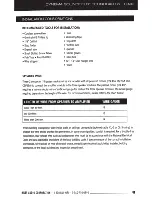
Page 9: ... gauge required depends on the length of the wire For recommendations please refer to the chart below LENGTH OF WIRE FROM SPEAKER TO AMPLIFIER WIRE GAUGE Less Then 80 Feet 18 80 200 Feet 16 More than 200 feet 14 When running loudspeaker wire inside walls or ceilings use special jacketed cable CL 2 or CL 3 rating to protect the wire and to provide fire prevention In some municipalities conduit is r...

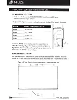
Page 10: ...A 3 3 4 X62 1 411 Aminimum of 3 1 2 depth inside the wall when measured from the interior face of the drywall plus 3 of clearance inside the wall below the top edge of the bottom mounting rail is required for proper clearance of the Speaker Module s Rear Wave Control enclosure IN WALL MOUNTING SYSTEM 3 7 6cm The Cynema Soundfield s In wall Mountirl System is uniquely designed to install as asingle...

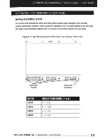
Page 11: ... of the TV s relative position to the wall studs see page 12 for installation exceptions that are affected by the relative position of the wall studs Figure 2 55 Wall Mounting System centered below aTV and shown without Grille Screw Down Brackets MODEL CSF48P CSF48A CSF55A CSF65A Studs H i Hioi Clamp Down End Bracket GRILLE DIMENSIONS HxW 5 1 411 X 4811 5 1 411 x4811 5 1 411 X 5511 5 1 411 X 6511 ...

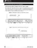
Page 12: ...The 65 model does not require this consideration due to its larger size Figure 3 48 System with the TV center 3 3 4 from the center of awall stud I Minimum Offset from Stud s Centerline TV relative to Flatpanel s Centerline and still I Centerline being able to center Grille with Flatpanel I 3 3 4 1 Figure 4 55 System with the TV center 1 4 from the center of the astud 1V Centerline 1 Minimum Offse...

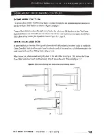
Page 13: ...amping the drywall as shown in Figure 2on page 11 SPECIAL INSTALLATION NOTE In some installations the ends of the top and bottom rails will fall too close to the side of astud to provide the Clamp Down End Bracket with enough drywall for clamping and at the same time not fall close enough to the stud to use the Screw Down Sliding Bracket Figure 5 A When this occurs attach awood furring strip flush...

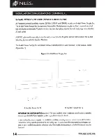
Page 14: ... below or directly behind awall mounted TV next to an AC outlet Figure 6A B Figure 6 In Wall Power Supply Box J loy I A Located Below the TV B Located Behind the TV IMPORTANT INSTALLTION NOTE Because the 24V DC cable provided is limited in length and cannot be spliced or extended you must locate the In Wall Power Supply Box as close as possible to the Amplifier Module In some municipalities condui...

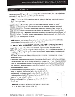
Page 15: ...ELS 1 Locate all of the studs in the wall below the lV location using astud sensor or by hand knocking 2 Drill a1 8 pilot hole just barely through the wallboard or dry wall 1 2 to 5 8 deep in most homes in the vertical center of your proposed speaker location and the horizontal center of each stud bay the mounting system will cover NOTE BE VERY CAREFUL NOT TO DRILL THROUGH EXISTING WIRES PIPES OR ...

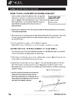
Page 16: ...Do not plug in the AC power cord until all other system connections are complete ASSEMBLE AND INSTALL THE IN WALL MOUNTING SYSTEM ALL MODELS 1 Determine the number of Screw Down Slide Brackets needed for In Wall Mounting System by counting the number of wall studs that are exposed within the drywall cutout 2 Slide the Screw Down Slide Brackets onto the Top and Bottom Rails as shown in Figure 7 and...

Page 17: ... Connection Route the supplied Toslink Optical cable or the Stereo 3 5mm to dual RCA Cable or HDMI cables from the TV to the Amplifier Module If necessary utilize the space between the Screw Down Slide Brackets and the wall stud to route the wires from one stud to another see Figure 8 ExternaiiR Receiver In the event that the IR signal to the amplifier module itself is being obstructed or interfer...

Page 18: ...aker as far to left as possible 1 Rotate the left and right L brackets out to serve as hangers from the In Wall Mounting System Hang the Speaker Modules in the position that they will be inserted as shown in Figure 9 Speaker Module Amplifier Module Left L Bracket Figure 9 Speaker and Amplifier Module CONNECT THE SPEAKER MODULES ALL MODELS 1 Prepare the speaker wire by stripping 1 4 1 2 from each c...

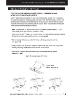
Page 19: ...ers and or insulation it is recommended to provide aminimum of 1 25 mm clearance between the vapor barrier insulation and the housing of the amplifier 1 Rotate the left and right L brackets out to serve as hangers from the In Wall Mounting System Hang the Amplifier Module in the position it will be inserted as shown in Figure 9 2 Affix the Niles SWT to the backside of the SWT Bracket with the supp...

Page 20: ...ERS ALL MODELS The empty spaces that are created in the In Wall Mounting System in between the installed Speaker Modules and Amplifier Module are filled by the supplied In Between Covers and Joiners In Between Covers are pre scored and designed to be broken into the sizes needed to fill these variably sized spaces In Between Joiners are designed to cover the seams of adjacent In between Covers A3 ...

Page 21: ...ce as shown in Figure 14 Figure 14 Installing the Speaker Module A Insert B Rotate C Snap In Rails INSTALL THE AMPLIFIER MODULES POWERED MODELS The Amplifier Module snaps into the In Wall Mounting System and is held securely in the rails using spring clips built into the Amplifier Module enclosure 1 Lift the Amplifier Module hanging from the In Wall Mounting System and rotate the L brackets on the...

Page 22: ...ric scrim on the back side must first be removed Use several light coats sprayed from different sides and angles to cover all surfaces and not fill in any holes If you do fill some holes use compressed air to open them before the paint dries It may be helpful to dilute the paint INSTALLING THE GRILLE ALL MODELS The Speaker Grille magnetically attaches to the In Wall Mounting System Once in place t...

Page 23: ...t the In Between Joiners and Covers adjacent to the module requiring service using asmall slotted screw driver NOTE To remove aSpeaker and Amplifier Module installed in the same stud bay remove the Screw Down Slide Bracket from an adjacent stud 2 Grasp the side s of the Speaker or Amplifier Module and pull it forward and out of the In Wall Mounting System NILES AUDIO CORPORATION 1 800 BUY HIFI 1 7...

Page 24: ...ction of awhole house audio system The Niles SWT SWR Wireless Subwoofer system has dedicated connections on the Amplifier Module for audio signal and DC power Figure 17 Powered Cynema Soundfield System with Optical Audio Connection Note For MS220 Microsensor A3 5mm stereo jock must be used Blu ray Player Cable Box HDMI w lfilllllil liiiiiGI1i lliilllm OUT Optical Out O wwwwnwrww w MS220 I MicroSen...

Page 25: ...ods and Smart Phones or the connection of awhole house audio system The Niles SWT SWR Wireless Subwoofer system has dedicated connections on the Amplifier Module for audio signal and DC power Figure 18 Powered Cynema Soundfield System with Analog Audio Connection Note For MS220 Microsensor o3 5mm stereo jock must be used N E E Blu ray Player Cable Box Whole House Audio System OR r _iijltfMIIQ ii Q...

Page 26: ...t Phones or the connection of awhole house audio system The Niles SWT SWR Wireless Subwoofer system has dedicated connections on the Amplifier Module for audio signal and DC power Figure 19 Powered Cynema Soundfield System with HDMI Connection Note For MS220 Microsensor A3 5mm stereo jack must be used F Miii f iliijW i Hi 4 HDMil I Blu ray Player MS220 MicroSensor M I Cable Box HDMI OUT HDMI OUT W...

Page 27: ...g volume control and amplification AV components like Bluray and HD Satellite Cable Boxes connect with HDMI to the AV receiver which connects with HDMI to the TV Audio source components and audio accessories such as iPods smart phones and subwoofers are included for added listening options Figure 20 Passive Cynema Soundfield System In Wall Mounted System SW6 5 Compact Powered Subwoofer NILES AUDIO...

Page 28: ...ause the LED indicators to illuminate NOTE All of the LED indicators turn completely off after three seconds of operational inactivity to prevent distraction while viewing TV Figure 21 LED Indicator Descriptions NAME DESCRIPTION Asolid green Power LED indicates the Amplifier Module is ON Asolid red Power LED indicates the Amplifier Module is OFF Power LED Aflashing red Power LED indicates the ampl...

Page 29: ...Selection The Amplifier Module automatically selects the appropriate surround sound mode for the currently selected input as shown in Figure 22 below Figure 22 Surround Sound Modes NAME DESCRIPTION Optical HOMI Dolby Digital Line Dolby Pro Logic Aux Music Mode MANUAL CONTROL Power Button The Power Button toggles the Amplifier Module on and off NOTE The Amplifier Module will also always turn on whe...

Page 30: ...peaker volume Center Volume Down Lowers the Center speaker volume Right Volume Up Raises the Right speaker volume Right Volume Down Lowers the Right speaker volume Aux Selects the Aux Input Hotel Night Sound Volume is limited to 70 o of maximum and bass response is reduced Wide Audio Mode Creates perception of wider sound field AXantech IR Receiver s 3 5mm 3 conductor plug can be connected directl...

Page 31: ...ilt in IR receiver from about 1ft 30 em and press the corresponding Vol button 4times until the Power LED lights green This indicates that the Amplifier Module has learned the command 4 Repeat steps 1to 4to teach commands to the remaining functions Note for cable satellite users If you plan to use the universal remote supplied with your cable satellite box to operate your Cynema Soundfield System ...

Page 32: ...or your costs of removing and transporting the product for warranty service evaluation or installation of any replacement product provided under this warranty This Warranty will be void if the Serial Number on the product has been removed tampered with or defaced the product was not purchased from an authorized dealer or reseller THE FOREGOING WARRANTIES ARE EXCLUSIVE AND IN LIEU OF ALL OTHER EXPR...

Page 33: ...CYNEMA SOUNDFIELD SOUNDBAR SYSTEMS CONTACT INFORMATION productsuggestions nilesaudio com NILES AUDIO CORPORATION 1 800 BUY HIFI 1 760 710 0992 33 ...

Page 34: ......

Page 35: ... v Ll J J z 0 a u I z a a 0 w I I ...

Page 36: ...anty does not cover reimbursement for your costs of removing and transporting the product for warranty service evaluation or installation of any replacement product provided under this warranty This Warranty will be void if the Serial Number on the product has been removed tampered with or defaced the product was not purchased from an authorized dealer or reseller THE FOREGOING WARRANTIES ARE EXCL...

Page 37: ...NILES THE FIRST NAME IN CUSTOM INSTALLATION 1 800 BUY H IF I 707 766 2503 www n i lesa ud io com 2013 Core Brands 1800 South McDowell Blvd Petaluma CA 94954 All rights reserved WR00009 ...

Reviews: