Service Manual-AS1050R
04 Control System 32
Specifications
Sample Shop Voltage Measurement
The following tables contain some “real world” shop voltage measurements to help you recognize what “normal” looks like.
•
Unless otherwise noted, all voltage readings are referenced to the main ground lug in the electrical bay.
•
Some pin numbers are listed out of sequence when measurements require pin-to-pin voltage references instead of the
main ground lug.
•
Values of “≈36V” represent full battery voltage, regardless of the circuit path.
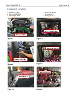
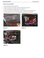
Please refer to Figure 1 and Figure 2 for connectors location on Dash Board (EB1) and Main Controller (EB2).
Figure 1. Connectors on Dash Board (EB1)
Dash Board (EB1) P1&P5 Connector
Pin#
Color
Function
Condition
Value
1
BLK
Ground
0V
2
BRN
CAN-H
≈2.56V
3
WHI
CAN-L
≈2.54V
4
RED
Power Input 36V
Key switch on
≈36V
Key switch off
0V
Summary of Contents for 50000593
Page 11: ...Service Manual AS1050R 03 General Information 11 Machine Structure Figure 2 ...
Page 12: ...Service Manual AS1050R 03 General Information 12 Machine Structure continues Figure 3 ...
Page 13: ...Service Manual AS1050R 03 General Information 13 Control Panel Figure 4 ...
Page 15: ...Service Manual AS1050R 03 General Information 15 Dimensions continues ...


