Service Manual- AS1050R
14 Wheels System 47
14 Wheel System-Traction
Functional Description
The traction motor (M1) drives the rear wheels of machine to propel it.
The speed limit potentiometer (VR1) enables operator to adjust the maximum forward and reverse speed of machine at
its full throttle. The speed of traction motor is controlled by throttle pedal. When Dash Board (EB1) receives information
from speed limit potentiometer (VR1) it will transmit it to Main Controller (EB2) via CAN Bus. The higher voltage the
pedal outputs, the faster the speed is. The pedal has a hall effect angle sensor and a micro-switch that are activated
when pedal is first pressed. When pressing pedal, the input of P2-7 change from 20V when at rest to 0V. Then Main
Controller (EB2) controls the electromagnetic brake (KA1) to enable motor to run. The dead band voltage range of pedal
output is 0-1.5V. The machine will not begin to move until the pedal output voltage is above 1.5V.
There is a reverse button on Dash Board (EB1). When it is pressed, the buzzer sounds and Dash Board (EB1) will send
the reverse command via CAN-BUS to Main Controller (EB2), then the output voltage of Main Controller (EB2) to both
ends of traction motor will be reversed, thus achieving reverse operation of traction motor.
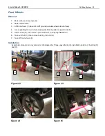
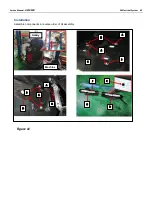
There are 2 proximity sensors (SQ1&SQ2) which monitor a steel plate attached to front wheel assembly and pivots with
it. See SQ1&SQ2 assembly diagram below.
The purpose of these inputs is to slow machine transport speed when turning for safety. When machine is moving straight
ahead, the steel plate is near each sensor and the sensor output to Main Controller (EB2) is 12V. When steering between
16-30 degrees to either left or right, the steel plate is no longer near SQ2 and its output changes to 0V. Consequently,
the machine transport speed will be reduced to 65% of maximum speed. When steering angle exceeds 30 degrees, the
steel plate is no longer near SQ1 and SQ2, and their output changes to 0V. Consequently, the machine transport speed
will be reduced to 40% of maximum speed. There are LED indicators on SQ1&SQ2 sensors. When output is 12V, LED
is on; when output is 0V, LED is off. See table below.
Steering Angle
SQ1 Output Volts
SQ2 Output Volts
Maximum Transport Speed
0-15 degrees (Straight)
12 V (LED on)
12 V (LED on)
100%
16-30 degrees
12 V (LED on)
0 V (LED off)
65%
>30 degrees
0 V (LED off)
0 V (LED off)
40%
When seat switch (SW7) is off, LCD will display
“stop”, and traction motor will be disabled.
When brake switch (SW6) is on,
LCD will display “brake Icon”, and traction motor will be disabled.
SQ1
SQ2
Steel plate
Summary of Contents for 50000593
Page 11: ...Service Manual AS1050R 03 General Information 11 Machine Structure Figure 2 ...
Page 12: ...Service Manual AS1050R 03 General Information 12 Machine Structure continues Figure 3 ...
Page 13: ...Service Manual AS1050R 03 General Information 13 Control Panel Figure 4 ...
Page 15: ...Service Manual AS1050R 03 General Information 15 Dimensions continues ...


