Service Manual-
AS1050R
24 Electrical System 59
Component Locations
•
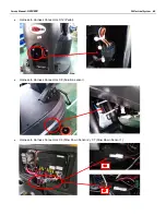
Dash Board (EB1)
•
Battery (BAT)
•
Battery connector
•
Dash Board circuit breaker (5A) (F1)
•
External charger connector (C5)
•
Key switch (SW2)
•
Emergency switch (SW1)
•
Charger sensor switch (SW3)
Figure 2
Figure 3
Figure 4
Figure 5
Figure 6
Dash Board (EB1)
Battery (BAT)
Battery connector
Dash Board circuit breaker (5A) (F1)
Key switch (SW2)
Emergency switch (SW1)
External charger connector (C5)
Figure 7
Charger sensor
switch (SW3)
Summary of Contents for 50000593
Page 11: ...Service Manual AS1050R 03 General Information 11 Machine Structure Figure 2 ...
Page 12: ...Service Manual AS1050R 03 General Information 12 Machine Structure continues Figure 3 ...
Page 13: ...Service Manual AS1050R 03 General Information 13 Control Panel Figure 4 ...
Page 15: ...Service Manual AS1050R 03 General Information 15 Dimensions continues ...


