
Wheel System - Traction
114
Service Manual – SC1500
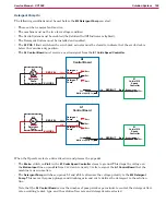
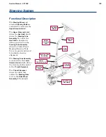
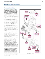
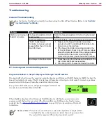
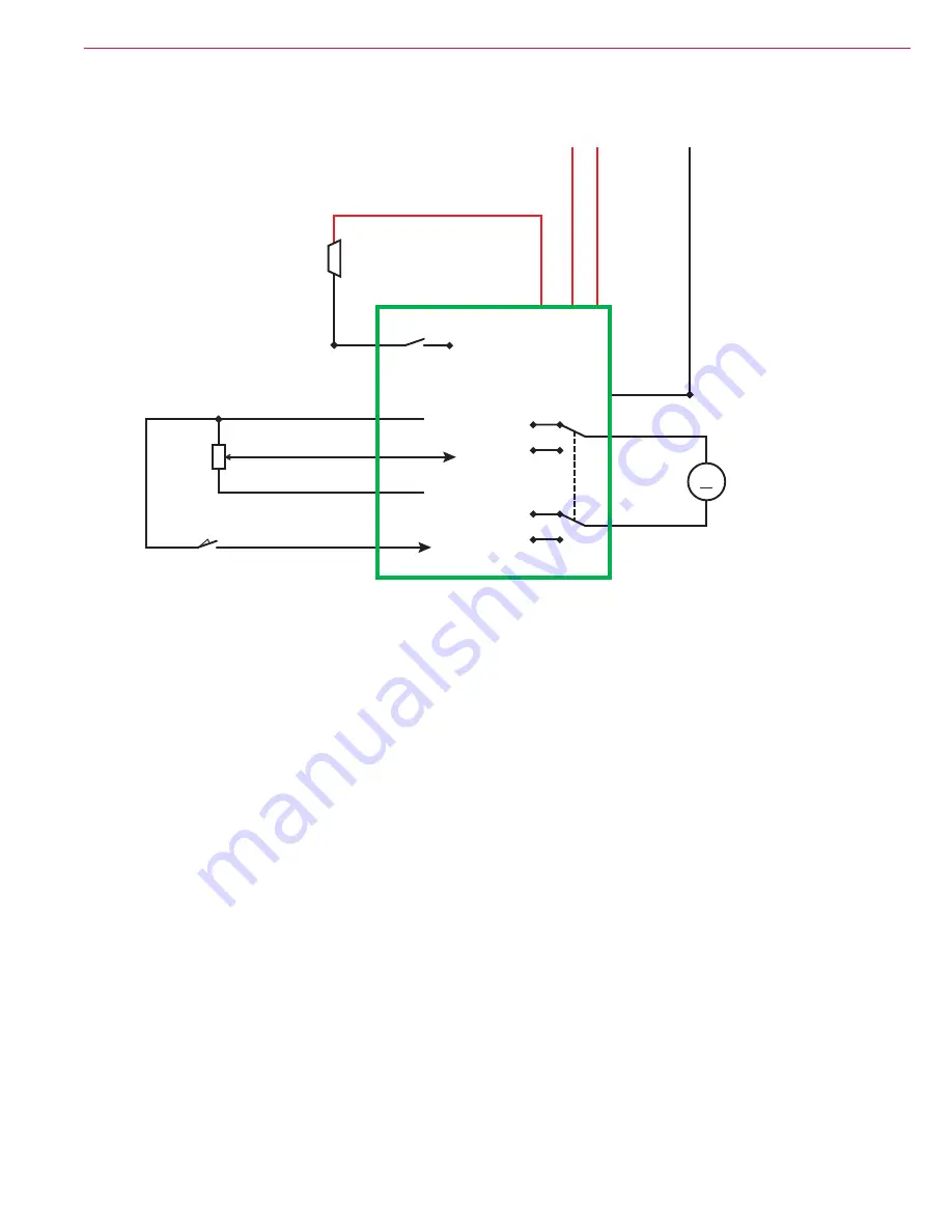
Speed Control Drive Functions
The
E1 Curtis 1210 Speed Controller
provides a regulated 5-volt supply out
Pin 3 - High
to the
100K Pot.
(speed
potentiometer) and the
Go Switch S5
. When the Operator steps on the Go Pedal, the
Go Switch
closes and
sends the 5 volts back to
Pin 4 - Pot. Wiper
on the
Speed Controller
Pin 13 - Pot. Low
supplies an internal connection to battery negative inside the
Speed Controller
The
100K Pot.
sends a variable voltage signal BACK to the
Speed Controller
at
Pin 18 - Speed Limit
The
Speed Controller
provides a power supply out
Pin 14 - +24V Brake +
to the
Y1 Brake
solenoid.
Just before the
Speed Controller
provides power to the
Wheel Drive Motor
, it provides a path to ground for the
electric
Y1 Brake
at
Pin 6 - Brake -
to energize the brake solenoid and release the brake. (The brake is spring-
loaded and will apply whenever the brake solenoid is not energized.)
B-
B+
B+
Y1
Brake
E1 Curtis 1210
Speed Controller
ORN
2
1
Brake -
Pin 6
YEL
YEL
VIO
YEL/BLK
RED/GRN
BLK
BLK
Wheel Drive
Motor
GRA
BLU
BLK
Pin 3
High
Pin 18
B-
B-
B+
B-
B+
Pin 14
Pin 5
B+
Brake +
KSI
+24V
+5V
Pot. Low
B-
Speed
Limit
B-
Pin 13
Pot. Wiper
Pin 4
2
GRN/ORG
100K Pot.
S5
R1
Go Switch
2
1
1
1
2
3
M1
M1
M2
M


