
Wheel System - Traction
128
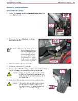
Service Manual – SC1500
6
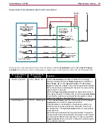
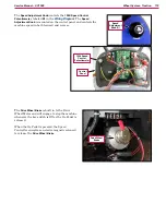
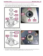
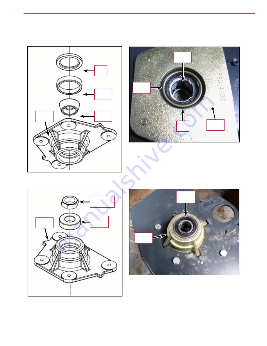
Carefully remove the Shaft Seal, Bearing Cup and Bearing Cone from the Bearing Block.
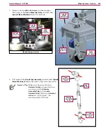
7
Replace the Shaft Seal, Bearing Cup or Bearing Cone as necessary. Make sure the Bearing Cone is
greased adequately with a high-quality lithium-base grease before reassembly.
Bearing
Cone
Bearing
Cup
Shaft
Seal
Bearing
Block
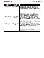
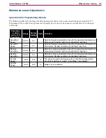
Shaft
Seal
Bearing
Cone
Bearing
Cup
Bearing
Block
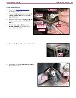
8
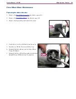
Remove and replace the Ball Bearing as necessary.
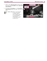
9
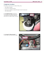
Reassemble the Drive Wheel Assembly by following the above steps in reverse order. Note that when you
reinstall the 1”-14 Nyloc
®
Nut onto the Spindle Weldment, torque the Nut to 20 ft.-lbs.
1”- 14
Nyloc
®
Nut
Ball
Bearing
Bearing
Block
Ball
Bearing
Bearing
Block


