Control System
41
Service Manual – SC1500
Panel Test
The
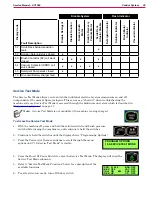
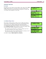
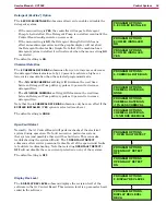
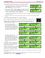
19. PANEL TEST
submenus allow you to verify the function of the control
panel membrane switches and LEDs, This will help identify any intermittent
or non-functioning switches or LEDs. When the submenu is first entered, all
LED will turn off
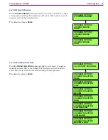
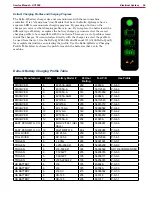
When you press a membrane switch, the display will show the name of
the switch on the line below
PANEL TEST
. The display shows that the
HORN
Switch has been pressed twice in this example.
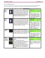
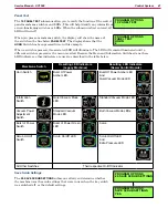
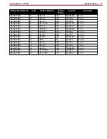
When a switch is pressed, its associated LED will illuminate. The LED will remain illuminated until a
different switch is pressed or the menu is exited. Because the Horn and Information Switches do not have
LED indicators, other indicators are used, as described in the table below.
Membrane Switch
Resulting LED Indicators
(Legacy Machines)
Resulting LED Indicators
(Newer Control Boards)
Horn Switch
Burst Of Power
Amber LED.
Burst Of Power Amber LED.
And
Quiet Vacuum Mode LED
Information
Switch
Quiet Vacuum Mode
LED
Standard Vacuum Mode LED
Vacuum Power
Adjustment
Switch
Standard Vacuum
Mode LED
Both Vacuum Mode LEDs
Burst of Power
Switch
Burst of Power Green
LED
Same
Scrub On/Off
Switch
Scrub On/Off LED
Scrub On/Off LED
And
Extra Pressure LED
All Other Switches
Their respective On/Off Indicator
Save Scrub Settings
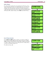
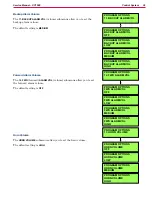
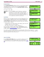
The
20. SAVE SCRUB SETTINGS
submenus allow you determine whether
the machine uses the scrub settings that were in use when the key switch
was switched off, or the default settings.
PROGRAM OPTIONS
19. PANEL TEST
PROGRAM OPTIONS
PANEL TEST
HORN
2
PROGRAM OPTIONS
SAVE SCRUB SETTINGS
YES
PROGRAM OPTIONS
20. SAVE SCRUB SETTINGS