Control System
45
Service Manual – SC1500
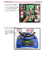
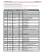
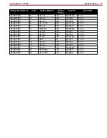
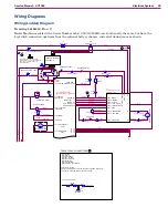
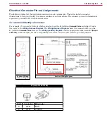
A1 Control Board Shop Measurements
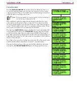
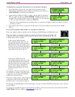
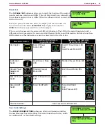
The following table lists measurements taken from one SC1500. While these are not “specifications”, they
can help you recognize abnormal vs. normal conditions.
Note that the black voltmeter lead is on B- unless otherwise indicated.
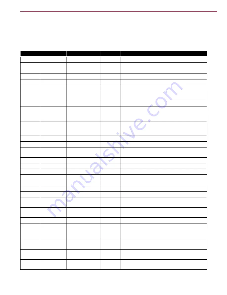
Pin
Color
Description
Ref.
Measurements
J1-1
RED/YEL
Chemical Pump +
B-
2.1v not on
J1-2
-
J1-3
BLU/GRY
Chemical Pump
B-
2.1v not on
J1-4
-
J1-5
-
J1-6
-
J1-7
RED/YEL
Inhibit SPC
B-
0.001v no direction selected
23.2v FWD or REV requested
J1-8
BLK
B-
0.09v Vacuum on
J1-9
BLU
Brush Act. -
B-
2.1v or 3.8v at rest
0.2v extending
22.9v retracting
J1-10
ORN/BLK
Brush Act. +
B-
2.1v or 3.8v at rest
0.2v retracting
22.9v extending
J2-1
BLK
B-
B-
0.09v Vacuum On
J2-2
BLK
B-
B-
0.09v Vacuum On
J2-3
ORN
Batt. Chg. Comm.
B-
0.8v key off
Plug in Charger: 12v, then 3.9v, then 12 v
J2-4
-
J2-5
-
J2-6
-
J2-7
BLK
B-
B-
0.09v Vacuum On
J2-8
BLK
B-
B-
0.09v Vacuum On
J2-9
-
J2-10
-
J2-11
BLK/WHT
Act. Position 2
B-
4.99v switch open
0.03v switch closed
J2-12
RED/VIO
Act. Position 1
B-
4.99v switch open
0.03v switch closed
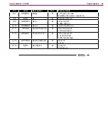
J3-1
BRN/VIO
B+
B-
24.5v key off or on
J3-2
-
J3-3
RED/BRN
Reverse
B-
0v no direction request or forward request
23.1v reverse direction request
J3-4
BRN
Dead Man Switch
B-
24.4v when pressed (Key and Emergency Switch
also closed)
J3-5
BLU/BLK
Rev. Alarm
B-
23.4v forward or stationary
1.5v in reverse
J3-6
RED/WHT
Motion
B-
24v stationary
0.1v moving forward or reverse


