
Electrical System
49
Service Manual – SC1500
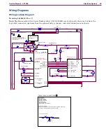
BT1
Battery 24 VDC
+
-
RED
BLK
Emergency
Stop
S4
S1
S2
Dead Man Switch
K
L
B
O
I
V
/
N
R
B
D
E
R
Circuit Breaker, 5 Amp
SPST Key
Switch
2
2
2
2
1
1
1
1
J2-3 Bat Charger
On-board Communication
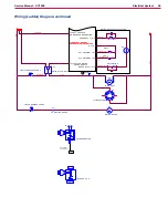
CB2
YEL/ORN
YEL/ORN
Gnd
1 2 3
A
B
B+ B-
RED
F1
Fuse, 150 A.
1
2
A1
Control Board
Main Machine
Controller
E1
Curtis 1210
Speed
Controller
Pin 5 - KSI
BRN
Dead Man
Switch J3-4
Internal Relay
in Battery Charger
Not Used
Not Used
Charter Interlock Circuit, Plugged In
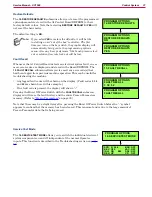
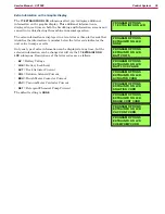
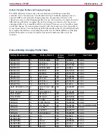
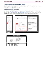
S.P.E. Charging Profiles and Charging Progress
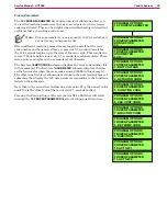
When the S.P.E. battery charger is plugged in, the graphic
display will show the charging profile in use, and a battery icon
with 0 to 5 bars to show the charging progress.
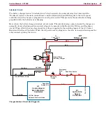
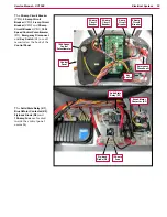
The S.P.E. battery charger and A1 Control Board communicate with one another on the YEL/ORN wire
that runs between them. Each time the battery charger is plugged in, the charger contacts the Controller
by sending out a positive voltage on the communication wire to find out what kind of batteries are in the
machine. It needs to know this in order to use the correct charging profile. The Controller responds and
provides the battery type information it has stored in memory. The charger then tells the Controller which
charging profile it will use and begins charging the batteries.
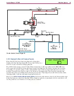
Refer to the
Control System/Programming Options
section for information on how to tell the controller what
kind of batteries are used in the machine. If the charger is unable to communicate with the controller it will
use the profile for a wet battery at a 25-amp rate as a default.


