22 - FORM NO. 56043089 / AquaRide
™
/ BRX 700
WHEEL DRIVE SYSTEM
STEERING SPINDLE AND WHEEL DRIVE MOTOR ASSEMBLY REMOVAL
WARNING!
Turn the main key switch (J) to the off position and disconnect the battery pack by pushing in the emergency disconnect lever (13).
Next block both rear wheels so machine can’t roll.
1 See Figures 6 & 7. Remove the brake foot pedal (A) secured by the (2) screws (D) that fasten the pedal mount bracket to the chassis allowing
access to the spindle retainer nut.
2 Pull out the brake rod (E) and use a 1-7/16” socket to remove the large spindle nut (F) from its shaft.
3
From underneath the front of the machine loosen the (4) (G) screws and push the lower steering column to the rear of the machine. This is done
to separate the chain (H) from the steer sprocket (I). Service Note: Use a 5/8” socket with 3” extension to remove screws and also correctly
position the large hole in the steer plate (J) in order to access the far back left screw.
4 On the right side of the drive motor remove the motor wiring cover and observe the (2) wires (red/green & yellow/black) attached to the motor
terminal connections for reassembling. Then remove the wires using a 13mm wrench.
5 Remove the (1) socket head cap screw (use a 3mm hex wrench) that retains the motor wiring harness P-clamp, then pull wiring to the rear of
the machine.
WARNING!
Never work under machine without safety stands or blocking to support the machine.
6
Safely jack up or lift the front of the machine to a height of approximately 16 inches (41 cm) to remove the wheel motor spindle assembly. Place
wood blocking under both front frame legs to support machine when removing the wheel /spindle assembly. Service Note: Be careful not to
damage the threads and bearing surfaces when guiding the spindle shaft down through the frame opening.
7 Inspect bearings and shaft seal and replace as needed.
8 To remove the steer spindle weldment (K) you must remove the steer plate (J) (with splash fender) held by (4) (L) fl at head socket screws (use
a 5 mm hex wrench) then separate the brake return spring and lay these removed parts to the side. Next remove the (4) item (M) fl at head
socket screws (55mm length) then fi nish removing the spindle weldment.
9 See
the “Drive Tire Removal” section for further disassembly steps.
10 Re-assemble in reverse order and tighten the spindle shaft nut (F) to 20ft/lbs (27 Nm) to eliminate any bearing play.
FIGURE 5
DRIVE TIRE REMOVAL
1 Follow the steps 1-8 in the “Steer Spindle and Wheel Drive Motor Assembly Removal” section.
2 See Figure 6. Remove the Retaining Ring (O) from the brake Pivot Pin (N). Then slide the pin out of the brake lever and support mount being
careful not to lose the washer which goes between them.
3 Carefully separate (tap off) the motor end bell housing (P) from the main motor case. Service Tip: To remove the housing use a brass drift or
piece of hard wood and strike the end bell edge evenly at points 120 degrees apart to slowly work it from the motor bearing.
4 Using a 5mm hex key wrench remove the (8) socket cap screws (Q) that secure the drive tire (R) to the motor drive hub and complete the tire
removal.
5 Install a new drive tire and tighten (torque) the (8) socket cap screws (Q) to 12 Ft/Lbs (16.2 N/M). Service Tip: Apply a small amount of Loctite
242 to all the cap screws to prevent the fasteners from backing out.
6 Re-assemble in reverse order following all the steps outlined in the steer spindle and drive motor removal section.
FRONT
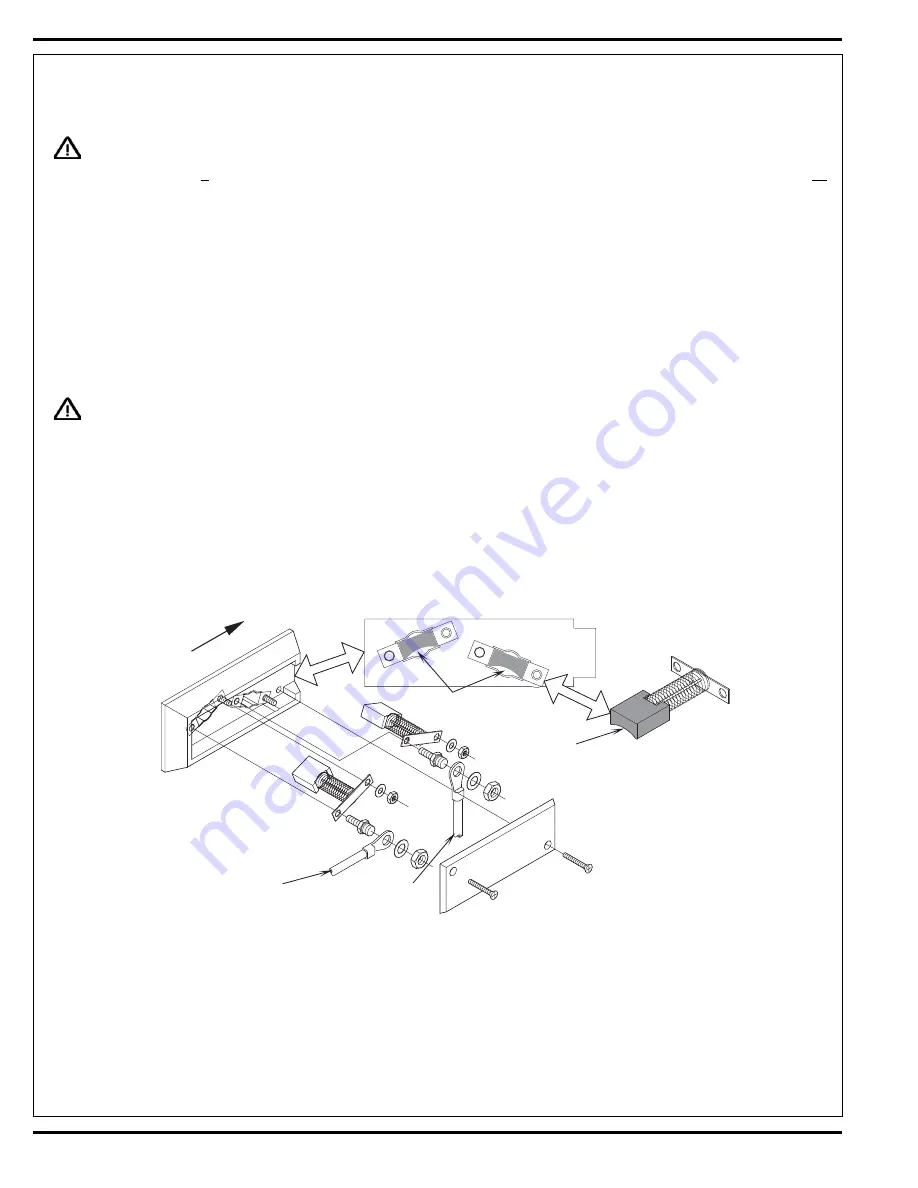
Yel/Blk
W ire
Red/Grn
W ire
Radius
Radius
Summary of Contents for 56314019
Page 7: ...FORM NO 56043089 AquaRide BRX 700 5 SPECIFICATIONS ...
Page 46: ...44 FORM NO 56043089 AquaRide BRX 700 RECOVERY SYSTEM FIGURE 3 ...
Page 49: ...RECOVERY SYSTEM FORM NO 56043089 AquaRide BRX 700 47 FIGURE 5 FIGURE 6 ...
Page 55: ...ELECTRICAL SYSTEM FORM NO 56043089 AquaRide BRX 700 53 FIGURE 4 FIGURE 3 ...
Page 72: ...70 FORM NO 56043089 AquaRide BRX 700 ELECTRICAL SYSTEM Drive Motor Breakdown ...
Page 79: ......
Page 82: ...www nilfisk advance com 2005 ...


