SOLUTION SYSTEM
FORM NO. 56043089 / AquaRide
™
/ BRX 700 - 37
MAJOR COMPONENTS SPECIFICATIONS
Nozzle and Pump Data
Flow Rate
Components
GPM / Working Pressure
Nozzle (A) “Maintenance”
.55 GPM
Spec. .057” orifi ce diameter
Hardened Stainless Steel
Nozzle tip I.D. QSTK-SS-3.0
Nozzle (B) “Restoration”
.98 GPM
Spec. .091”orifi ce diameter
Brass
Nozzle tip I.D. QTKA-BR7.5
Pump Specifi cations
Pressure relief switch opens at 100 PSI
Max.
fl ow rate 1.6 GPM
Max. current 3A (average current 2.7A)
NOZZLE MAINTENANCE
See Figure 4. To inspect and clean both nozzles no tools are needed. First remove the Wing Nut (G) that secures the nozzle bracket (tree) and
pull it from the brush housing slots with the hoses still connected.
To remove a nozzle to clean or replace just grip the nozzle tip and at the same time press in and twist it a 1/4 turn to separate it from the nozzle
body. Note: Suggested once a week to inspect and clean nozzles.
Clean by soaking nozzles overnight in a full strength vinegar solution or properly diluted and handled meratic acid solution to remove build up of
chemical deposits. Note: Do not ream out (increase) the orifi ce by cleaning with a drill bit. As this will affect the nozzle working pressure and spray
pattern.
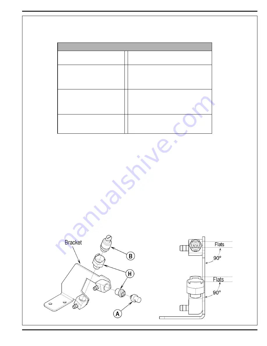
NOZZLE FIXTURE INSTALLATION
1 Apply small amount of thread sealant (Loctite #242-blue) to the fi xture threads.
2 See Figure 3. Thread the Nozzle Fixtures (H) into each brass barb.
3 Position
nozzle
fi xture as shown (nozzle fi xture fl at must be 90º to bracket arm).
FIGURE 3
Summary of Contents for 56314019
Page 7: ...FORM NO 56043089 AquaRide BRX 700 5 SPECIFICATIONS ...
Page 46: ...44 FORM NO 56043089 AquaRide BRX 700 RECOVERY SYSTEM FIGURE 3 ...
Page 49: ...RECOVERY SYSTEM FORM NO 56043089 AquaRide BRX 700 47 FIGURE 5 FIGURE 6 ...
Page 55: ...ELECTRICAL SYSTEM FORM NO 56043089 AquaRide BRX 700 53 FIGURE 4 FIGURE 3 ...
Page 72: ...70 FORM NO 56043089 AquaRide BRX 700 ELECTRICAL SYSTEM Drive Motor Breakdown ...
Page 79: ......
Page 82: ...www nilfisk advance com 2005 ...


