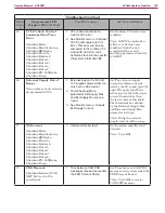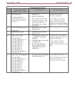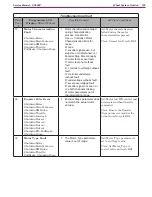
Wheel System, Traction
185
Service Manual – SC6500
™
an additional dedicated wire for this circuit and it works in the same way as the “Motion” circuit. When the
vehicle is moving forward, the switch is open and the input is high. When the vehicle is moving in reverse,
the switch closes, causing the input to go low.
Fault Circuit
The wheel drive controller informs the “main” (A2) Control Board when it has set a fault code using a single
wire that functions much like the motion and direction circuits.
Mode 1 and Mode 2 Circuits
The (A2) “main” Control Board informs the wheel drive controller how it wants it to control the drive wheel
using two circuits “mode 1” and “mode 2”. Each circuit is a logic circuit where the voltage is either low or
high. The drive speed is normally slowed down while scrubbing unless the operator chooses to press the
scrub speed switch to increase the speed. The operator can also request reduced torque and speed on slippery
surfaces using the traction control switch.
Potentiometer
The drive pedal has a three wire potentiometer attached to its side. The potentiometer tracks the angle or
“position” of the drive paddle. The A1 Wheel drive controller supplies a 5 volt potential across the resistive
strip of the potentiometer on the “POT high” and “POT low” wires. The “POT wiper” circuit returns a portion
of the voltage back to the A1 wheel drive controller as an analog input which is proportional to the position
of the pedal. The potentiometer is part of a new drive pedal assemble and comes pre-adjusted from the
factory.
Motor Temperature Sensor
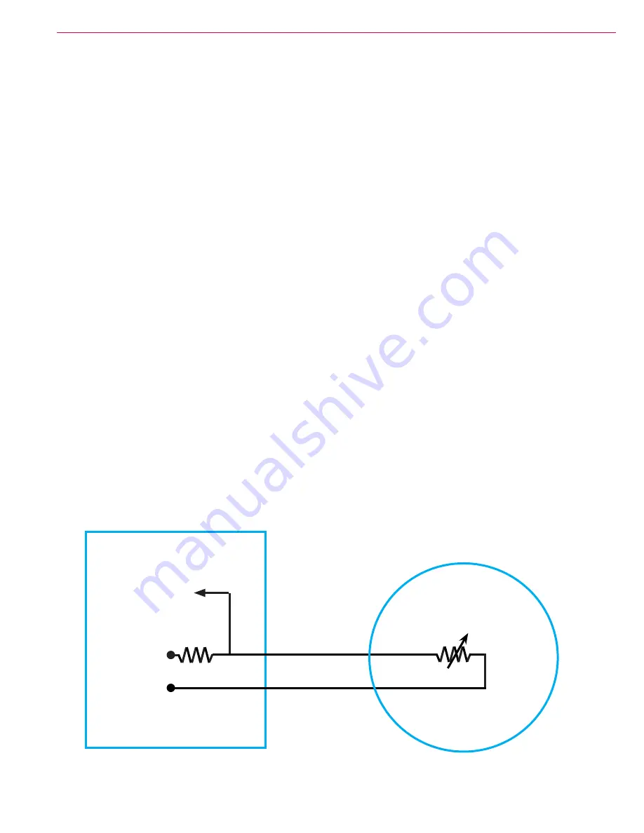
The motor temperature sensor is a negative temperature coefficient thermistor It has two wires. One
is connected to battery negative inside the wheel drive controller. The other is a 5 volt supply through
a resistor from the controller. The controller reads the voltage between the internal resistor and the
temperature sensor.
Input
+ 5V
B-
Temperature Sensor
Wheel Drive Controller
Wheel Drive Motor


