Wheel System, Traction
183
Service Manual – SC6500
™
Wheel Motor, Temp Sensor and Encoder
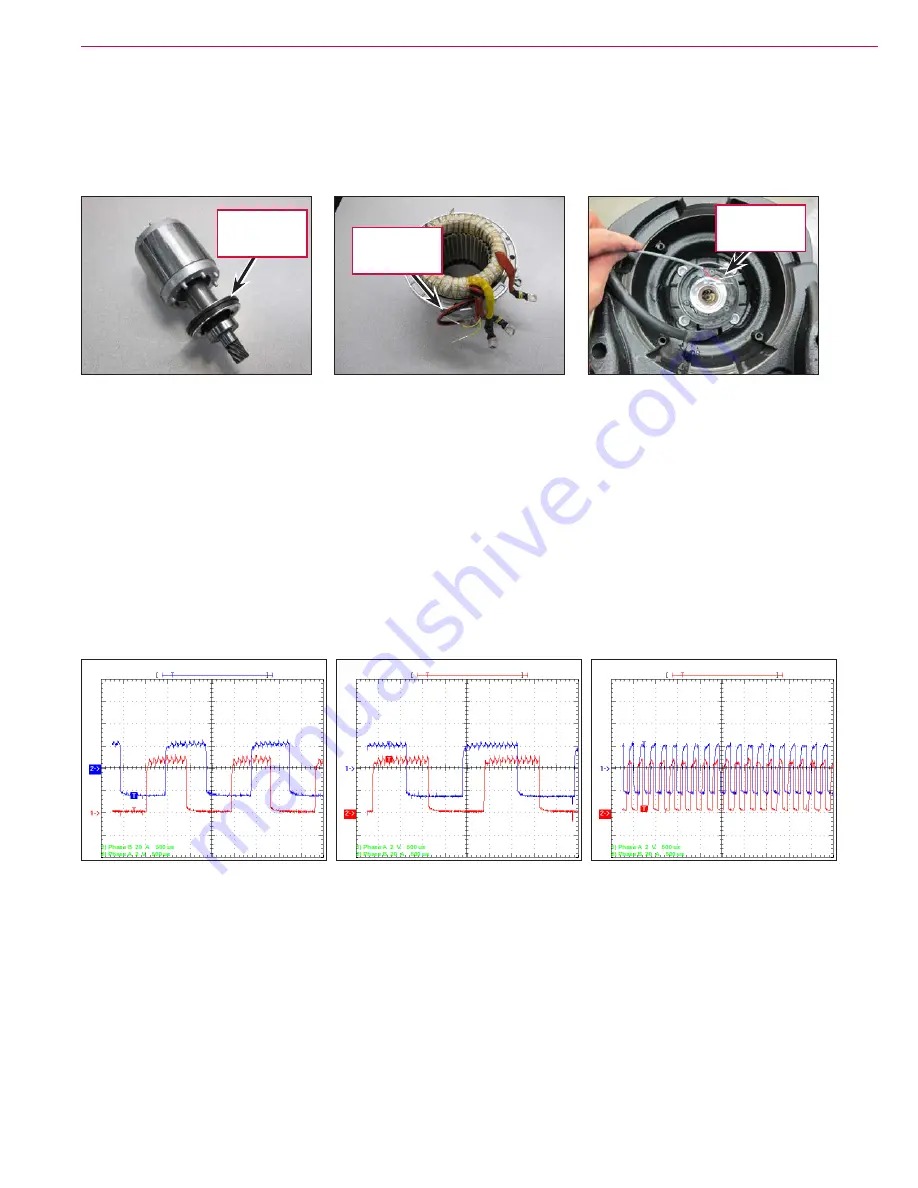
The drive wheel motor assembly contains an AC motor, temperature sensor and an encoder. The AC motor
consists of an outer stator and a rotor. The temperature sensor is embedded in the stator windings. There is
a magnetic ring attached to the rotor. The encoder is attached to the gearbox case and “reads” the magnetic
ring as it spins with the rotor.
Figure 4: Rotor with magnetic Ring
Figure 5: Stator with temp sensor
Figure 6: Encoder
Magnetic ring
Temperature
sensor wires
Encoder and
wiring
The motor stator windings are connected to the U, V and W cables, which are attached directly to the wheel
drive controller. The wheel drive controller energizes the motor stator windings in a timed sequence to
simulate a magnetic field moving around the outer perimeter of the motor. This moving magnetic field acts
upon the armature causing it to rotate.
An encoder inside the drive wheel motor serves as the “eyes” of the wheel drive controller so that it can see
if the motor turned in the direction that it was trying to move it and how fast it is moving. The encoder is
a solid state “sensor”which converts motor rotation into a pair of 5 volt square wave patterns. The encoder
reads the magnetic ring that is attached to the rotor and spins with the rotor. The patterns are offset so that
the controller can “see” which direction the motor is rotating. See Figure 7 showing the blue pattern to the
right of the red one when moving forward. See Figure 8 showing the blue pattern to the left fo the red one
Figure 7: Encoder, forward
Figure 8: Encoder, reverse
Figure 9: Encoder, increased speed


