background image

2

FLOORTEC 350

146 3083 000(2)2008-11 A

ENGLISH

USER MANUAL

INTRODUCTION

NOTE

The numbers in brackets refer to the components shown in Machine Description chapter.

MANUAL PURPOSE AND CONTENTS

The purpose of this Manual is to provide the operator with all necessary information to use the machine properly in a safe and 
autonomous way. It contains information about technical data, safety, operation, storage, maintenance, spare parts and disposal.

%HIRUHSHUIRUPLQJDQ\SURFHGXUHRQWKHPDFKLQHWKHRSHUDWRUVDQGTXDOL¿HGWHFKQLFLDQVPXVWUHDGWKLV0DQXDOFDUHIXOO\&RQWDFW

1LO¿VNLQFDVHRIGRXEWVFRQFHUQLQJWKHLQWHUSUHWDWLRQRIWKHLQVWUXFWLRQVDQGIRUDQ\IXUWKHULQIRUPDWLRQ

TARGET

7KLV0DQXDOLVLQWHQGHGIRURSHUDWRUVDQGWHFKQLFLDQVTXDOL¿HGWRSHUIRUPWKHPDFKLQHPDLQWHQDQFH

7KHRSHUDWRUVPXVWQRWSHUIRUPSURFHGXUHVUHVHUYHGIRUTXDOL¿HGWHFKQLFLDQV1LO¿VNZLOOQRWEHDQVZHUDEOHIRUGDPDJHVFRPLQJ

from the non-observance of this prohibition.

HOW TO KEEP THIS MANUAL

The User Manual must be kept near the machine, inside an adequate case, away from liquids and other substances that can cause 
damage to it.

DECLARATION OF CONFORMITY

7KHGHFODUDWLRQRIFRQIRUPLW\VXSSOLHGZLWKWKHPDFKLQHFHUWL¿HVWKHPDFKLQHFRQIRUPLW\ZLWKWKHODZLQIRUFH

NOTE

Two copies of the original declaration of conformity are provided together with the machine documentation.

IDENTIFICATION DATA

The machine model and serial number are marked on the plate (33).

7KHPDFKLQHPRGHO\HDULVZULWWHQLQWKHGHFODUDWLRQRIFRQIRUPLW\DQGLWLVDOVRLQGLFDWHGE\WKH¿UVWWZR¿JXUHVRIWKHPDFKLQH

serial number.

7KLVLQIRUPDWLRQLVXVHIXOZKHQUHTXLULQJPDFKLQHVSDUHSDUWV8VHWKHIROORZLQJWDEOHWRZULWHGRZQWKHPDFKLQHLGHQWL¿FDWLRQGDWD

MACHINE model  ...............................................................................

MACHINE serial number  ...................................................................

Summary of Contents for 908 4704 010

Page 1: ...EC 350 Instructions for use Model 908 4704 010 08 2006 Revised 11 2008 2 146 3083 000 Deutsch Français English Nederlands Bedienungshandbuch Instructions d utilisation Instructions for use Gebruiksaanwijzing ...

Page 2: ...rdo con le VHJXHQWL GLUHWWLYH H VWDQGDUG O IDVFLFROR WHFQLFR q UHGDWWR GDO FRVWUXWWRUH Toliau pateiktu dokumentu patvirtinama NDG PLQơWDV PRGHOLV UD SDJDPLQWDV ODLNDQWLV QXURG Wǐ GLUHNW Yǐ EHL VWDQGDUWǐ 7HFKQLQĊ E Oą VXGDUơ JDPLQWRMDV U ãR WLHN DSOLHFLQƗWV ND DXJVWƗNPLQƝWDLV PRGHOLV LU L JDWDYRWV DWELOVWRãL ãƗGƗP GLUHNWƯYƗP XQ VWDQGDUWLHP 7HKQLVNR DSUDNVWX LU VDVWƗGƯMLV UDåRWƗMV Undertegnede attes...

Page 3: ...SORIES OPTIONS 7 TECHNICAL DATA 7 WIRING DIAGRAM 8 USE 9 BATTERY CHECK ON A NEW MACHINE 9 BEFORE STARTING THE MACHINE 9 STARTING AND STOPPING THE MACHINE 9 MACHINE OPERATION 10 HOPPER EMPTYING 10 AFTER USING THE MACHINE 10 MACHINE LONG INACTIVITY 10 FIRST PERIOD OF USE 10 MAINTENANCE 11 SCHEDULED MAINTENANCE TABLE 11 BATTERY CHARGER CABLE CHECK 11 SIDE BROOM HEIGHT CHECK AND ADJUSTMENT 12 SIDE BRO...

Page 4: ...QDQFH 7KH RSHUDWRUV PXVW QRW SHUIRUP SURFHGXUHV UHVHUYHG IRU TXDOL HG WHFKQLFLDQV 1LO VN ZLOO QRW EH DQVZHUDEOH IRU GDPDJHV FRPLQJ from the non observance of this prohibition HOW TO KEEP THIS MANUAL The User Manual must be kept near the machine inside an adequate case away from liquids and other substances that can cause damage to it DECLARATION OF CONFORMITY 7KH GHFODUDWLRQ RI FRQIRUPLW VXSSOLHG ...

Page 5: ...UHYLRXVO Q FKDQJH DQG RU DGGLWLRQ RI DFFHVVRU PXVW EH DSSURYHG DQG SHUIRUPHG E 1LO VN OPERATION CAPABILITIES 7KLV VZHHSHU KDV EHHQ GHVLJQHG DQG EXLOW WR FOHDQ E VZHHSLQJ DQG YDFXXPLQJ VPRRWK DQG VROLG ÀRRUV LQ FLYLO DQG LQGXVWULDO HQYLURQPHQWV DQG WR FROOHFW GXVW DQG OLJKW GHEULV XQGHU VDIH RSHUDWLRQ FRQGLWLRQV E D TXDOL HG RSHUDWRU CONVENTIONS Forward backward front rear left or right are intende...

Page 6: ...y for people CAUTION It indicates a caution or a remark related to important or useful functions Pay careful attention to the paragraphs marked by this symbol NOTE It indicates a remark related to important or useful functions CONSULTATION It indicates the necessity to refer to the User Manual before performing any procedure GENERAL INSTRUCTIONS 6SHFL F ZDUQLQJV DQG FDXWLRQV WR LQIRUP DERXW SRWHQW...

Page 7: ...e moving parts Do not wash the machine with direct or pressurised water jets or with corrosive substances Do not use compressed air to clean this type of machine While using this machine take care not to cause damage to other people and children especially R QRW SXW DQ FDQ FRQWDLQLQJ ÀXLGV RQ WKH PDFKLQH The machine storage temperature must be between 0 C and 40 C The machine working temperature m...

Page 8: ...r 6 Handlebar 7 Handlebar adjusting knobs 8 Filter shaker knob 9 Hopper 10 Front steering wheel 11 Side broom 12 Side broom lifting lowering lever 13 Side broom height adjusting knob 14 Main broom 15 Main broom height adjusting knobs 16 Rear driving wheels 17 Can holder 18 Battery charger cable 19 Battery charger cable housing 20 Side broom motor circuit breaker 21 Main motor circuit breaker 22 Ba...

Page 9: ...m size diameter x length 200 x 500 mm Side broom diameter 315 mm Main broom speed 335 rpm Side broom speed 100 rpm Gradeability 2 Hopper capacity 60 litres Total machine weight with standard battery 68 kg Front steering wheel size diameter x length 75 x 32 mm Rear wheel size diameter x length 300 x 45 mm Maximum drive speed 3 7 km h Sound pressure level at workstation ISO 11201 ISO 4871 LpA 59 3 3...

Page 10: ...charger EB1 Electronic board LED ES1 Relay F1 Main fuse F2 Vacuum fan fuse F3 Side broom fuse M1 Main motor M2 Vacuum system motor M3 Side broom motor SW1 Main switch SW2 Hopper microswitch Colour code BK Black BU Blue BN Brown GN Green GY Grey OG Orange PK Pink RD Red VT Violet WH White YE Yellow S311349 ...

Page 11: ...erwise install them see the procedure in Maintenance chapter STARTING AND STOPPING THE MACHINE Starting the machine 1 Adjust the handlebar 6 to reach a comfortable position by loosening the knobs 7 When the adjustment is completed tighten the knobs 2 To use the main broom only 14 turn the main switch 1 to I To use also the side broom 11 turn the main switch 1 to II then lower the side broom by dis...

Page 12: ... EMPTYING Stop the machine and turn the main switch 1 to 0 Remove the hopper 9 by using the handles 31 and 32 then empty it at the waste collection centre Then install the hopper The machine is ready to start working again NOTE When the hopper is removed all machine functions are disabled AFTER USING THE MACHINE After working before leaving the machine 1 Turn the main switch 1 to 0 2 7XUQ RQ WKH O...

Page 13: ...common maintenance procedures NOTE For other maintenance procedures shown in the Scheduled Maintenance Table refer to the Service Manual that can be consulted at any Service Center SCHEDULED MAINTENANCE TABLE Procedure Every 10 hours Every 50 hours Every 200 hours Every 400 hours Battery charger cable check Side and main broom height check and adjustment Skirt height and operation check XVW OWHU F...

Page 14: ... Turn the knob 13 clockwise and counter clockwise to adjust the broom height 3 Perform step 1 again to check the proper adjustment of the side broom height 4 When the broom is too worn to be adjusted replace it as shown in the next paragraph SIDE BROOM DISASSEMBLY ASSEMBLY CAUTION It is advisable to wear protective gloves when replacing the side broom because there can be sharp debris between the ...

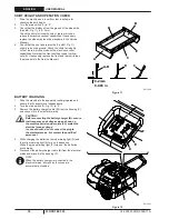
Page 15: ...loosen the knob A Fig 4 4 Grasp the support B on the points C and move it upwards then lift it or lower it to change the main broom height For height variation refer to the indicator D Then tighten the knob A on both sides of the machine 5 Perform step 1 again to check the proper adjustment of the main broom height 6 When the broom is too worn to be adjusted replace it as shown in the next paragra...

Page 16: ...machine 5 Remove the lid A Fig 6 by grasping it on the points B 6 Grasp the main broom A Fig 7 on the points B and C then disconnect it from the drive hub D by pulling it in WKH GLUHFWLRQ VKRZQ E WKH DUURZ WKHQ UHPRYH LW LQ WKH direction shown by the arrow F 7 The new main broom must be installed with the bristles URZV EHQW DV VKRZQ LQ WKH JXUH 8 Install the new broom by performing steps 3 to 6 in...

Page 17: ...pressed air F at maximum 6 Bar blowing only from the side of the gasket E at a minimum distance of 30 cm KHFN WKH OWHU ERG IRU WHDUV I QHFHVVDU UHSODFH LW RU D EHWWHU FOHDQLQJ LW LV DOORZHG WR ZDVK WKH OWHU ZLWK water and non lathering detergents This provides better TXDOLW FOHDQLQJ EXW UHGXFHV WKH OLIH RI WKH OWHU ZKLFK will have to be replaced more frequently The use of LQDGHTXDWH GHWHUJHQWV FDQ...

Page 18: ...ATTERY CHARGING 1 Drive the machine to the appointed recharging area and ensure that it cannot move independently 2 Turn the main switch A Fig 12 to 0 3 Remove the battery charger cable B from the housing C and connect it to the electrical mains CAUTION Before connecting the battery charger B ensure that frequency and voltage values shown on the machine serial number plate 33 match the electrical ...

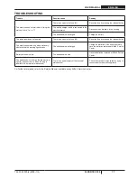
Page 19: ...y pressing the relevant button The machine operates only when stationary otherwise the red warning light turns on The batteries are discharged Charge the batteries If the trouble persists KDYH WKH EDWWHULHV UHSODFHG DW 1LO VN 6HUYLFH Center Battery autonomy is low The batteries are dead DYH WKH EDWWHULHV UHSODFHG DW 1LO VN 6HUYLFH Center The batteries do not charge the red warning light 4 does not...

Page 20: ...HU Before scrapping the machine remove and separate the following materials which must be disposed of properly according to the Law in force Battery Brooms Plastic hoses and components Electrical and electronic components 5HIHU WR WKH QHDUHVW 1LO VN HQWHU HVSHFLDOO ZKHQ VFUDSSLQJ HOHFWULFDO DQG HOHFWURQLF FRPSRQHQWV ...

Reviews: