104
Service Manual – SW5500, FLOORTEC R 985
20 - Wheel System, Traction
Shop Measurements - Drive Wheel Controller (EB2) (continues)
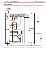
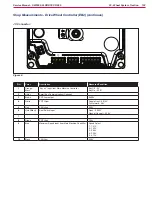
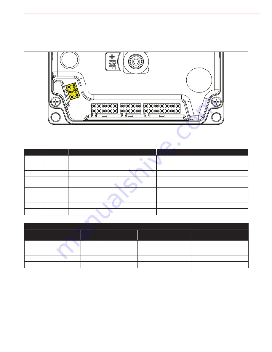
JD Connector:
JD
Figure 9:
PIN
Color
Description
Measured/Condition
1
Blue
Encoder Phase A
13.5V or 0.135V depending on location. You can move
the wheel slightly by hand to confirm that it switches.
Rotating - 6.7V Average
2
Red
Encoder positive supply
13.4V
3
Yellow
Motor Temp. Sensor input
1.38V @ 26 Deg C.
12.1V when circuit is open
4
White
Encoder Phase B
13.5V or 0.135V depending on location. You can move
the wheel slightly by hand to confirm that it switches.
Rotating - 6.7V Average
5
Black
Encoder negative supply
0.005V
6
Yellow/Black
Motor Temp. Sensor negative reference
0.005V
High Current Cables
Measurment points
Stationary
Low Speed
No load
Full Speed Forward
No load
U to V
U to W
V to W
1.0 mVAC
0 HZ
2.4 VAC
HZ 3.7 KHZ
19.12 VAC
105 HZ
Battery Positive to B+
0.005V
Battery Negative to B-
0.069V

