76
Service Manual – SW5500, FLOORTEC R 985
05 - Control System
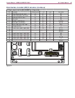
Shop Measurements - Main Machine Controller (EB1) (continues)
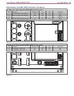
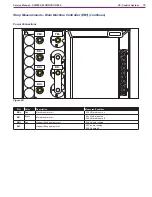
J3: Signal inputs / outputs connections
J3
Figure 48:
J3
PIN
Color
Description
Measured/Condition
1
Blue
Main Control board serial connection
4.09V
2
Yellow
Main Control board serial connection
2.4 - 2.7V
3
4
Main Control board power supply -
0.004V
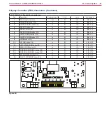
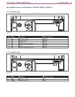
J4: Signal inputs / outputs connections
J4
Figure 49:
J4
PIN
Color
Description
Measured/Condition
1
Black
Electromagnetic switch output -
Key on 23.5V initially
Drops to 0.056V when it turns on
2
Red
Electromagnetic switch
22.7V


