INSTRUCTIONS FOR USE
9096910000(1)2006-09
9
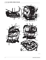
Solution front filler neck (37)
- For easily filling the tank with solution.
Foam filter (38)
- It prevents debris or foreign materials from entering into the tank.
Compensation hole (39)
- Keep it clean, for an efficient vacuuming of the recovery water.
Recovery water tank (open) (40)
- Empty and lift it to reach the batteries and the detergent tank.
Tank lifting handle (41)
- Grasp it to lift the tank, only when it is empty.
Tank safety cable (42)
- It keeps the tank opened.
Vacuum system motor cover (43)
- It retains the sound-deadening filter and protects the vacuum system motor.
Vacuum system motor sound-deadening filter (44)
- It protects the motor from debris and foreign material, and it deadens
the vacuum system motor noise.
Detergent tank (*) (45)
- It contains the detergent that will be mixed with the clean water.
Detergent tank filler plug (*) (46)
- Open it to pour the detergent in the tank. Use only low-foam detergents.
Detergent tank handle (*) (47)
- Use it to lift/lower the tank.
Detergent supply hose to brushes (*) (48)
- It supplies the detergent to the brushes.
Detergent pump (*) (49)
- It vacuums the detergent from the tank and supplies it, together with the clean water, to the brushes.
Water pump (*) (50)
- It vacuums the water from the tank and supplies it to the brushes.
Clean water filter (*) (51)
- It filters clean water before supplying it to the pump and to the brushes.
Batteries (52)
- They supply current for machine operation. The machine can be equipped with lead (WET) or gel (GEL)
batteries.
Battery caps (53)
- WET batteries are equipped with caps for maintenance purposes.
Solution filter (54)
- It filters the solution before supplying it to the solenoid valve and to the brushes.
Solution/clean water tap (55)
- It closes the solution/clean water flow.
Solenoid valve (56)
- It controls the water flow. If the machine is equipped with AXP it works as a tap.
Reference table for detergent proportioning (*) (57)
- It indicates the percentages of detergent in the washing water. The
same percentages are shown by the flow indicator (82c).
(*)
Only for
X20D
,
X20C
,
X24D
.
(**) If the machine is equipped with AXP [switch (77) (optional) enabled] pour clean water in the tank, otherwise pour solution.
(***) Only for deck with one brush/pad-holder.
CONTROL AND SWITCH DESCRIPTION
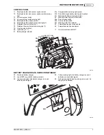
Brush/pad-holder and vacuum system switch (71)
- It turns on the brushes/pad-holders and the vacuum system. When
pressed twice, it turns off the brushes/pad-holders. To turn off the vacuum system, press the switch (73).
Vacuum system switch (73)
- It turns the vacuum system on and off.
Brush/pad-holder release switch (75)
- It releases the brushes/pad-holders, and it can be pressed only when the
brushes/pad-holders are off.
Detergent flow control switch (*) (77)
- It turns the AXP on and off and it allows to change the detergent concentration.
Ignition key (80)
- It turns the control panel on and off.
Washing water flow control switches (82)
- To control the detergent quantity supplied to the brushes.
Flow increase switch (82a)
- It increases the water quantity supplied to the brushes.
Flow decrease switch (82b)
- It decreases the water quantity supplied to the brushes.
Washing water flow indicator (82c)
- It shows the water quantity supplied to the brushes.
Drive paddle (83)
- Push it forward to move the machine forward, push it backwards to move the machine in reverse. The
brushes/pad-holders and the water flow turn on only when the paddle is pushed in either directions. When the paddle is
released, the brushes/pad-holders turn off.
Forward/reverse gear speed adjuster (84)
- It adjusts the machine maximum speed, when the drive paddle is pushed to the
end of stroke.
(*)
Only for machines with AXP


