5/00 revised 5/22/00 Form No. 56040719
© 2000 Nilfisk-Advance, Inc. Printed in USA
(page 1 of 3)
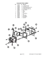
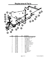
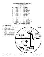
56419213 CAB BLOWER KIT
For Retriever™ 2060G, P, D, DU and Nilfisk SR 1800G, P, D, DU
CONTENTS OF KIT
ITEM
PART NO.
QTY
DESCRIPTION
56040719
1
Instruction Sheet
1
56002063
2
Wsh, Flt SAE 3/8
2
56002098
4
Wsh, Flt SAE 1/4
3
56002663
2
Scr, Hex Hd 3/8-16 x 1.00
4
56002667
2
Scr, Hex Hd 5/16-18 x .75
5
56002701
2
Nut, Hex Nyl Loc 5/16-18
6
56002769
2
Nut, Hex Nyl Loc 3/8-16
7
56003454
4
Scr, Hex Thd to Hd SS M6-1.0x 20MM
8
56009250
6
Scr, Hex Thd Form1/4-20 x .62
9
56323092
1
Strain Relief
10
56352829
4
Clamp, Hose SAE #52
11
56207077
1
Switch, Toggle DPST
12
56419214
1
Cab Fan Assembly
13
56419216
1
Seal, Bubble
14
56419217
1
Air Cleaner
15
56419218
1
Clamp, Air Cleaner
16
56419219
1
Bracket, Fan Mounting
17
56419220
1
Hose 3 Dia x 5.0
18
56419221
1
Tube Weldment
19
56419223
2
Elbow
20
56419236
1
Bracket, Switch
21
56900229
1
Fuse, 10 Amp
INSTALLATION INSTRUCTIONS
WARNING!
DISCONNECT BATTERY BEFORE SERVICING.
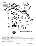
1
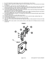
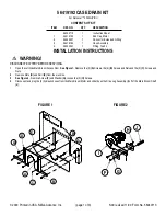
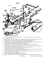
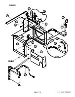
See Figure 1. Fasten Fan
(12)
to the Fan Mounting Bracket
(16)
using four Screws
(7)
and four Washers
(2)
.
2
Install the Seal
(13)
onto the fan inlet, with the bulb toward the inside.
3
Assemble Air Cleaner
(14)
to Fan Mounting Bracket
(16)
using Air Cleaner Clamp
(15)
and two Screws
(4)
and two Nuts
(5)
. Push the air cleaner
into the fan inlet and Seal
(13)
before tightening air cleaner clamp
(15)
. Then tighten the clamp at the fan inlet that came with the fan.
4
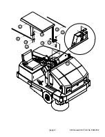
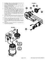
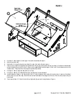
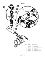
Locate the two mounting holes in the rear of the upper left side corner of the cab. Remove any screws currently in these holes. Use two Screws
(4)
and Nuts
(5)
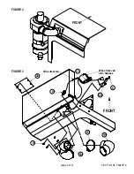
to install air cleaner and fan assembly to the cab. Figure 2 shows the blower installed on the cab.
5
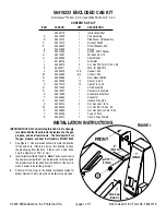
Trim 1.25” (3.2 cm) off the end of one of the Elbows
(19)
as shown in Figure 1. Then install the elbow to the Air Cleaner
(13)
with Hose Clamp
(10)
.
Rotate the elbow down until it’s touching the window. This is to allow the engine hood to open.
6
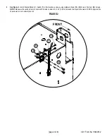
Remove the small rectangular plate near the top of the cab (4 screws).
7
Install the Tube Weldment
(18)
to the cab as shown, using four Screws
(8)
.
8
Install the Hose
(17)
between the fan and the Tube Weldment
(18)
using two Hose Clamps
(10)
.
9
Use a hose clamp to install the remaining Elbow
(19)
to the Tube Weldment
(18)
inside the cab. Turn the elbow to get the desired direction of
airflow.
10
Fasten the Strain Relief
(9)
to the .75” (19 mm) diameter hole in the tube weldment.
11
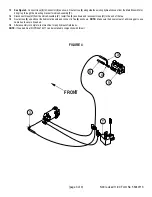
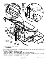
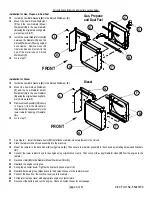
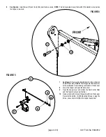
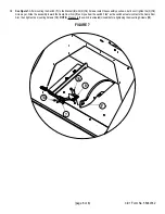
See Figure 3. Feed the fan’s wiring through the strain relief, to the inside of the cab.
12
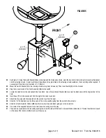
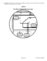
Position the Switch Bracket
(20)
in a desired location, between the corner and where the tube weldment directs the air flow into the cab. Mark the
position for the two holes needed to mount the switch bracket.
13
Drill the two holes marked in the previous step to a diameter of .228” (5.8mm).
Summary of Contents for Advance Retriever 2060
Page 87: ...4 99 Form No 56040696 page 2 A 3 B C D 5 1 2 6...
Page 94: ...6 99 revised 3 00 Form No 56040702 page 2 5 3 2 6 6 5 3 4 1 2...
Page 111: ...9 00 Form No 56040733 page 2 of 3 Diesel H FRONT M K L N R W P O T S J Q O P U V FIGURE 1...
Page 128: ...PROGRAM PURPOSE and OBJECT ZENITH FUEL SYSTEMS Page 1 1 5 48 7 0 1 2 3 4 5 0 50...
Page 133: ...ZENITH FUEL SYSTEMS Page 5 1 5 0 50 A 50 4 4 B 8 6 A C D FIG 5 1...
Page 134: ...ZENITH FUEL SYSTEMS Page 5 2 6 5 8 0 8 2 0 2 0 2 E F 0 D 50 4 C D 5 5 5 5 6 6 2 0 6 FIG 5 2...
Page 139: ...Fuel Enrichment 4 6 6 50 5 5 6 A 50 5 0 0 ZENITH FUEL SYSTEMS Page 5 7...
Page 144: ...ZENITH FUEL SYSTEMS INC Page 5 12 3F 6 6 H J 3F FIG 5 19 6 G 6 FIG 5 20...
Page 147: ...ZENITH FUEL SYSTEMS Page 6 2 A A 1 6 FIG 6 1...
Page 148: ...ZENITH FUEL SYSTEMS Page 6 3 5 2 3 0 0 1 4 4 B 6 6 6 4 4 3 6 6 6 9 6 6...
Page 149: ...ZENITH FUEL SYSTEMS Page 7 2 8 2...
Page 150: ...ZENITH FUEL SYSTEMS Page 7 3 8 2...
Page 153: ...ZENITH FUEL SYSTEMS Page 9 3...
Page 160: ...ZENITH FUEL SYSTEMS Page 9 11 6 6 9 8 2...
Page 163: ...ZENITH FUEL SYSTEMS Page 9 14 6 6 9 8 Continued...

