16
-
FORM NO. 56043051 / Retriever
™
2060
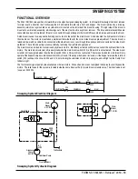
SWEEPING SYSTEM
U
T
R
Q
S
FRONT
K
N
J
M
O
L
I
P
M
________________________________________________________________________________________________________________________________________________________________________________________________________________________________________________________________________
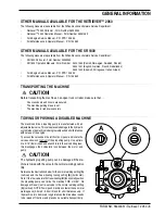
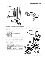
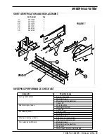
SIDE BROOM MAINTENACE
To adjust the Side Broom . . .
1
Put the side broom in the DOWN position.
2
See Figure 4. Loosen the Handle
(V)
and slide the Stop Bracket
(W)
up or down to lower or raise the Side Broom
(13)
. The farther
the Lever
(17)
travels up in the slot, the lower the Side Broom
(13)
will be.
3
When in the Down position, the Side Broom
(13)
should be contacting the floor from the 10 O’clock
(X)
to the 3 O’clock
(Y)
area
shown.
4
Once the Side Broom
(13)
is properly adjusted, tighten the Handle
(V)
to secure the Stop Bracket
(W)
.
________________________________________________________________________________________________________________________________________________________________________________________________________________________________________________________________________
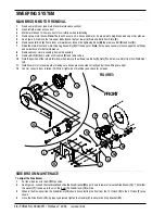
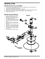
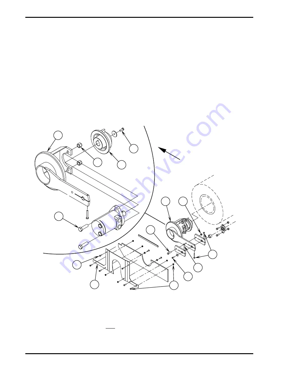
MAIN BROOM MOTOR REMOVAL
1
Remove main broom (see main broom maintenance section)
2
Open left side lower access door.
3
Mark motor hoses to insure correct motor rotation when reinstalling.
4
Remove two motor hoses.
Note:
There will be some oil in hoses and motor, be prepared to plug hoses and cap motor elbows.
5
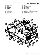
See Figure 3. Remove the two upper Bolts
(I)
and the four lower
(J)
Nuts and Bolts from Plate
(K)
.
6
Remove center Bolt
(L)
from broom arm weldment, loosen the tightening Bolts
(M)
then remove Bolt
(N)
and Nut
(O)
.
7
Raise the main broom and work Drive Lug Assembly
(P)
off the hex arm.
Note:
It may be necessary to loosen upper hose fittings
and swivel hoses for better clearance.
8
Remove broom motor assembly from skirt assembly.
9
Remove Bolt
(Q)
from center of Drive Hub
(R)
and remove hub.
10
Note the position of the two motor elbows then remove the elbows, two Bolts
(S)
, Nuts
(T)
and remove motor from Arm Weldment
(U)
.
11
Install new motor in reverse order making sure hoses are connected correctly and all hose fittings are tight.
12
Test for correct broom rotation (CCW from right side of machine) and check for oil leaks.
FIGURE 3
revised 12/02
Summary of Contents for Advance Retriever 2060
Page 87: ...4 99 Form No 56040696 page 2 A 3 B C D 5 1 2 6...
Page 94: ...6 99 revised 3 00 Form No 56040702 page 2 5 3 2 6 6 5 3 4 1 2...
Page 111: ...9 00 Form No 56040733 page 2 of 3 Diesel H FRONT M K L N R W P O T S J Q O P U V FIGURE 1...
Page 128: ...PROGRAM PURPOSE and OBJECT ZENITH FUEL SYSTEMS Page 1 1 5 48 7 0 1 2 3 4 5 0 50...
Page 133: ...ZENITH FUEL SYSTEMS Page 5 1 5 0 50 A 50 4 4 B 8 6 A C D FIG 5 1...
Page 134: ...ZENITH FUEL SYSTEMS Page 5 2 6 5 8 0 8 2 0 2 0 2 E F 0 D 50 4 C D 5 5 5 5 6 6 2 0 6 FIG 5 2...
Page 139: ...Fuel Enrichment 4 6 6 50 5 5 6 A 50 5 0 0 ZENITH FUEL SYSTEMS Page 5 7...
Page 144: ...ZENITH FUEL SYSTEMS INC Page 5 12 3F 6 6 H J 3F FIG 5 19 6 G 6 FIG 5 20...
Page 147: ...ZENITH FUEL SYSTEMS Page 6 2 A A 1 6 FIG 6 1...
Page 148: ...ZENITH FUEL SYSTEMS Page 6 3 5 2 3 0 0 1 4 4 B 6 6 6 4 4 3 6 6 6 9 6 6...
Page 149: ...ZENITH FUEL SYSTEMS Page 7 2 8 2...
Page 150: ...ZENITH FUEL SYSTEMS Page 7 3 8 2...
Page 153: ...ZENITH FUEL SYSTEMS Page 9 3...
Page 160: ...ZENITH FUEL SYSTEMS Page 9 11 6 6 9 8 2...
Page 163: ...ZENITH FUEL SYSTEMS Page 9 14 6 6 9 8 Continued...

