18 - FORM NO. 56043051 / Retriever
™
2060
SWEEPING SYSTEM
FRONT
JJ
II
FF
GG
HH
KK
________________________________________________________________________________________________________________________________________________________________________________________________________________________________________________________________________
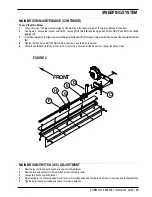
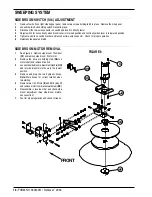
SIDE BROOM SWITCH (S14) ADJUSTMENT
1
Remove four bolts on right side hopper panel, remove two screws holding latch in place. Remove the side panel.
2
Loosen the two bolts holding switch bracket in place.
3
Disconnect the two-wire connector on switch and insert continuity tester.
4
Adjust switch for no continuity when broom lever is in raised position and continuity when lever is in lowered position.
5
Tighten two bolts on switch bracket and reconnect two-wire connector. Check for proper operation.
6
Reinstall side panel and latch.
________________________________________________________________________________________________________________________________________________________________________________________________________________________________________________________________________
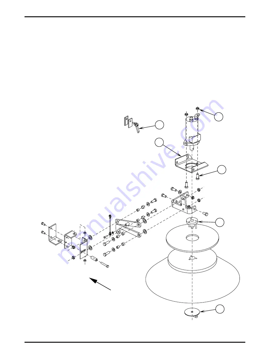
SIDE BROOM MOTOR REMOVAL
1
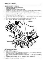
See Figure 6. Remove side broom Thumbnut
(FF) and remove side broom from motor.
2
Remove the drive pin holding Hub (GG) on
motor shaft and remove drive hub.
3
Loosen the side broom adjustment Handle (HH)
and let side broom motor down to the lowest
position.
4
Remove and plug the two hydraulic hoses.
Note: Mark hoses for correct rotation when
reinstalling.
5
Remove two 1/2-13 Nuts (II) and Bolts (JJ), lift
and remove motor from bracket weldment (KK).
6
Reassemble in reverse order and check side
broom adjustment. (See side broom mainte-
nance section)
7
Test for proper operation and check for leaks.
FIGURE 6
Summary of Contents for Advance Retriever 2060
Page 87: ...4 99 Form No 56040696 page 2 A 3 B C D 5 1 2 6...
Page 94: ...6 99 revised 3 00 Form No 56040702 page 2 5 3 2 6 6 5 3 4 1 2...
Page 111: ...9 00 Form No 56040733 page 2 of 3 Diesel H FRONT M K L N R W P O T S J Q O P U V FIGURE 1...
Page 128: ...PROGRAM PURPOSE and OBJECT ZENITH FUEL SYSTEMS Page 1 1 5 48 7 0 1 2 3 4 5 0 50...
Page 133: ...ZENITH FUEL SYSTEMS Page 5 1 5 0 50 A 50 4 4 B 8 6 A C D FIG 5 1...
Page 134: ...ZENITH FUEL SYSTEMS Page 5 2 6 5 8 0 8 2 0 2 0 2 E F 0 D 50 4 C D 5 5 5 5 6 6 2 0 6 FIG 5 2...
Page 139: ...Fuel Enrichment 4 6 6 50 5 5 6 A 50 5 0 0 ZENITH FUEL SYSTEMS Page 5 7...
Page 144: ...ZENITH FUEL SYSTEMS INC Page 5 12 3F 6 6 H J 3F FIG 5 19 6 G 6 FIG 5 20...
Page 147: ...ZENITH FUEL SYSTEMS Page 6 2 A A 1 6 FIG 6 1...
Page 148: ...ZENITH FUEL SYSTEMS Page 6 3 5 2 3 0 0 1 4 4 B 6 6 6 4 4 3 6 6 6 9 6 6...
Page 149: ...ZENITH FUEL SYSTEMS Page 7 2 8 2...
Page 150: ...ZENITH FUEL SYSTEMS Page 7 3 8 2...
Page 153: ...ZENITH FUEL SYSTEMS Page 9 3...
Page 160: ...ZENITH FUEL SYSTEMS Page 9 11 6 6 9 8 2...
Page 163: ...ZENITH FUEL SYSTEMS Page 9 14 6 6 9 8 Continued...

