FORM NO. 56043051 / Retriever
™
2060 - 33
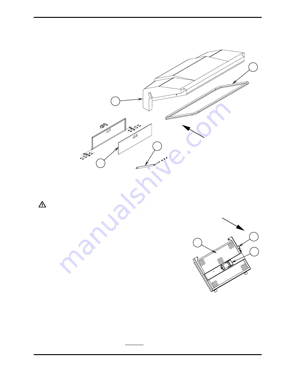
DUST CONTROL SYSTEM
FRONT
A
B
C
D
________________________________________________________________________________________________________________________________________________________________________________________________________________________________________________________________________
SEAL REPLACEMENT
Part Number
Qty
A
56418815
1
Gasket
B
56418172
1
Litter Door Gasket
________________________________________________________________________________________________________________________________________________________________________________________________________________________________________________________________________
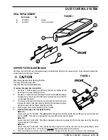
HOPPER FILTER MAINTENANCE
The hopper dust control filter must be cleaned regularly to maintain the efficiency of the vacuum system. Follow the recommended filter
service intervals for the longest filter life.
CAUTION!
Wear safety glasses when cleaning the filter.
Do not puncture the paper filter.
E
FRONT
F
G
FIGURE 2
FIGURE 1
Clean the filter in a well-ventilated area.
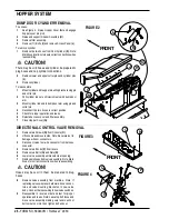
To remove the hopper dust control filter . . .
1
See Figure 1. Lift the Hopper Cover (C) on top of the hopper. Make sure that
the Hopper Cover Prop Rod (D) is in place.
2
See Figure 2. Inspect \ the top of the Hopper Dust Control Filter (E) for damage.
A large amount of dust on top of the filter is usually caused by a hole in the filter
or a damaged filter gasket.
3
Turn the two hold-downs to the side (one on each side at the front of the frame)
to release the shaker frame, then swing the Dust Filter Shaker Assembly (F) up
and latch in place with the Shaker Assembly Latch (G).
4
Lift the Hopper Dust Control Filter (E) out of the machine.
5
Clean the filter using one of the methods below:
Method “A”
Vacuum loose dust from the filter. Then gently tap the filter against a flat surface (with the dirty side down) to remove loose dust
and dirt. NOTE: Take care not to damage the metal lip which extends past the gasket.
Method “B”
Vacuum loose dust from the filter. Then blow compressed air (maximum pressure 100 PSI) into the clean side of the filter (in the
opposite direction of the airflow).
Method “C”
Vacuum loose dust from the filter. Then soak the filter in warm water for 15 minutes, then rinse it under a gentle stream of water
(maximum pressure 40 PSI). Let the filter dry completely before putting it back into the machine.
6
Follow the instructions in reverse order to install the filter. If the gasket on the filter is torn or missing, it must be replaced.
Summary of Contents for Advance Retriever 2060
Page 87: ...4 99 Form No 56040696 page 2 A 3 B C D 5 1 2 6...
Page 94: ...6 99 revised 3 00 Form No 56040702 page 2 5 3 2 6 6 5 3 4 1 2...
Page 111: ...9 00 Form No 56040733 page 2 of 3 Diesel H FRONT M K L N R W P O T S J Q O P U V FIGURE 1...
Page 128: ...PROGRAM PURPOSE and OBJECT ZENITH FUEL SYSTEMS Page 1 1 5 48 7 0 1 2 3 4 5 0 50...
Page 133: ...ZENITH FUEL SYSTEMS Page 5 1 5 0 50 A 50 4 4 B 8 6 A C D FIG 5 1...
Page 134: ...ZENITH FUEL SYSTEMS Page 5 2 6 5 8 0 8 2 0 2 0 2 E F 0 D 50 4 C D 5 5 5 5 6 6 2 0 6 FIG 5 2...
Page 139: ...Fuel Enrichment 4 6 6 50 5 5 6 A 50 5 0 0 ZENITH FUEL SYSTEMS Page 5 7...
Page 144: ...ZENITH FUEL SYSTEMS INC Page 5 12 3F 6 6 H J 3F FIG 5 19 6 G 6 FIG 5 20...
Page 147: ...ZENITH FUEL SYSTEMS Page 6 2 A A 1 6 FIG 6 1...
Page 148: ...ZENITH FUEL SYSTEMS Page 6 3 5 2 3 0 0 1 4 4 B 6 6 6 4 4 3 6 6 6 9 6 6...
Page 149: ...ZENITH FUEL SYSTEMS Page 7 2 8 2...
Page 150: ...ZENITH FUEL SYSTEMS Page 7 3 8 2...
Page 153: ...ZENITH FUEL SYSTEMS Page 9 3...
Page 160: ...ZENITH FUEL SYSTEMS Page 9 11 6 6 9 8 2...
Page 163: ...ZENITH FUEL SYSTEMS Page 9 14 6 6 9 8 Continued...

