FORM NO. 56043051 / Retriever
™
2060 - 43
STEERING SYSTEM
________________________________________________________________________________________________________________________________________________________________________________________________________________________________________________________________________
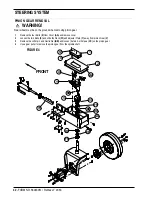
SPINDLE REMOVAL AND BEARING REPLACEMENT
WARNING!
Never work under a machine with out safety blocks and stands to support the machine.
1
Remove the key, set the parking brake and block the front wheels.
2
Remove the three hydraulic hoses on the drive motor.
CAUTION!
There may be oil in motor and hoses be prepared to plug hoses and cap motor connectors.
3
Remove cover Plate (AA).
4
Follow steps 1-4 in the pinion gear removal section.
5
Support the drive wheel/spindle assembly with a movable service jack. Using proper safety precautions, slowly raise the rear of
the machine with a hoist or jack, while moving the spindle assembly towards the rear of the machine. It is important that the spindle
shaft is kept at a right angle to the machine while the rear is being raised. NOTE: The rear of the machine will need to be raised
24 inches for the shaft to clear the frame with the rear wheel installed.
6
Place jack stands under the machine.
7
You now have access to the upper and lower bearing cones, cups and seals (DD, EE, FF). NOTE: If replacing bearings be sure
to pack bearing with grease before installing.
8
To reassemble, first install lower bearing cup, cone and seal into steering Casting (GG). Using a movable service jack guide the
spindle shaft through the lower bearing and steering casting. NOTE: It is important that the shaft goes through the lower bearing
as straight as possible, it may be easier to install the spindle with the tire removed from the spindle assembly.
9
Slowly lower the rear of the machine and the service jack until the machine is supported by the drive tire.
10
Install upper bearing cup, cone, seal, spacer and pinion gear.
11
Install and tighten the Castle Nut (BB).
12
With the steering wheel centered make sure the drive wheel is straight then follow steps 1-4 in the (To adjust) section.
________________________________________________________________________________________________________________________________________________________________________________________________________________________________________________________________________
TROUBLESHOOTING GUIDE
Problem
Possible cause
Slow steering, hard steering or loss of
Priority flow divider not providing 2 gpm.
Power assist.
1500 PSI relief valve open or
malfunctioning.
Steering wandering.
Rack and pinion worn or out of
adjustment.
Loose or leaking cylinder piston.
Steering control unit worn.
Steering wheel turns freely
Problem with steering column
without moving wheel.
Shaft or spline.
Steering binding.
Rack and pinion worn or out of
adjustment.
Steer cylinder loose.
Summary of Contents for Advance Retriever 2060
Page 87: ...4 99 Form No 56040696 page 2 A 3 B C D 5 1 2 6...
Page 94: ...6 99 revised 3 00 Form No 56040702 page 2 5 3 2 6 6 5 3 4 1 2...
Page 111: ...9 00 Form No 56040733 page 2 of 3 Diesel H FRONT M K L N R W P O T S J Q O P U V FIGURE 1...
Page 128: ...PROGRAM PURPOSE and OBJECT ZENITH FUEL SYSTEMS Page 1 1 5 48 7 0 1 2 3 4 5 0 50...
Page 133: ...ZENITH FUEL SYSTEMS Page 5 1 5 0 50 A 50 4 4 B 8 6 A C D FIG 5 1...
Page 134: ...ZENITH FUEL SYSTEMS Page 5 2 6 5 8 0 8 2 0 2 0 2 E F 0 D 50 4 C D 5 5 5 5 6 6 2 0 6 FIG 5 2...
Page 139: ...Fuel Enrichment 4 6 6 50 5 5 6 A 50 5 0 0 ZENITH FUEL SYSTEMS Page 5 7...
Page 144: ...ZENITH FUEL SYSTEMS INC Page 5 12 3F 6 6 H J 3F FIG 5 19 6 G 6 FIG 5 20...
Page 147: ...ZENITH FUEL SYSTEMS Page 6 2 A A 1 6 FIG 6 1...
Page 148: ...ZENITH FUEL SYSTEMS Page 6 3 5 2 3 0 0 1 4 4 B 6 6 6 4 4 3 6 6 6 9 6 6...
Page 149: ...ZENITH FUEL SYSTEMS Page 7 2 8 2...
Page 150: ...ZENITH FUEL SYSTEMS Page 7 3 8 2...
Page 153: ...ZENITH FUEL SYSTEMS Page 9 3...
Page 160: ...ZENITH FUEL SYSTEMS Page 9 11 6 6 9 8 2...
Page 163: ...ZENITH FUEL SYSTEMS Page 9 14 6 6 9 8 Continued...

