44 - FORM NO. 56043051 / Retriever
™
2060
BRAKING / FRONT WHEEL SYSTEM
A
FRONT
________________________________________________________________________________________________________________________________________________________________________________________________________________________________________________________________________
BRAKE ADJUSTMENT
The machines brake system employees a combined foot operated pedal and a hand parking brake lever assembly. A common link
weldment controls the input to a horizontal brake balance bar that operates the two front wheel brake assemblies.
To adjust the brakes:
1
The brake adjustment is normally done with the parking brake lever. The parking brake lever should be adjusted so it firmly holds
its (locked park) setting without easily being released.
2
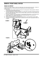
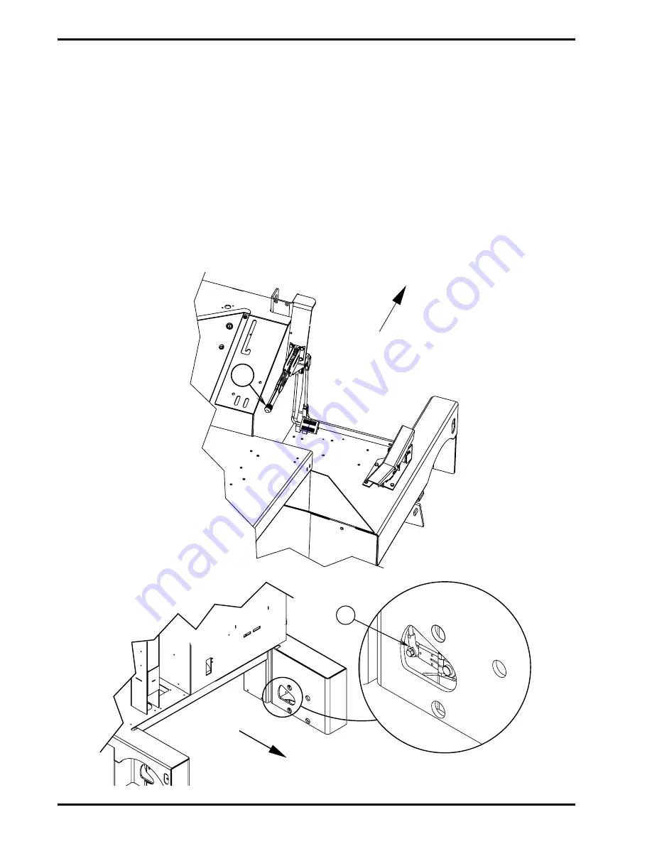
To adjust the parking brake, turn the handle Knob (A) (Figure 1) on the end of the lever clockwise to increase the brake locking
force. NOTE: If the knob adjustment is inadequate to firmly hold the brake setting, this indicates the need to inspect the brake shoes
and service if there is excessive wear.
3
The foot pedal normally does not need regular adjustment. The brake pedal should have about 2-2 1/4 inch of free play before
the brakes engage. If the foot pedal exceeds this distance, with the parking brake adjusted, follow the steps below.
4
Raise and support hopper. Turn engine off and remove key.
5
See Figure 2. Adjust Clevis (B) evenly on both wheels until foot pedal has 2-2 1/4 inch free play before the brakes engage.
6
After adjustment of either the pedal or parking brake lever always check the other components for proper operation and test-drive
the machine.
FIGURE 1
B
FRONT
FIGURE 2
Summary of Contents for Advance Retriever 2060
Page 87: ...4 99 Form No 56040696 page 2 A 3 B C D 5 1 2 6...
Page 94: ...6 99 revised 3 00 Form No 56040702 page 2 5 3 2 6 6 5 3 4 1 2...
Page 111: ...9 00 Form No 56040733 page 2 of 3 Diesel H FRONT M K L N R W P O T S J Q O P U V FIGURE 1...
Page 128: ...PROGRAM PURPOSE and OBJECT ZENITH FUEL SYSTEMS Page 1 1 5 48 7 0 1 2 3 4 5 0 50...
Page 133: ...ZENITH FUEL SYSTEMS Page 5 1 5 0 50 A 50 4 4 B 8 6 A C D FIG 5 1...
Page 134: ...ZENITH FUEL SYSTEMS Page 5 2 6 5 8 0 8 2 0 2 0 2 E F 0 D 50 4 C D 5 5 5 5 6 6 2 0 6 FIG 5 2...
Page 139: ...Fuel Enrichment 4 6 6 50 5 5 6 A 50 5 0 0 ZENITH FUEL SYSTEMS Page 5 7...
Page 144: ...ZENITH FUEL SYSTEMS INC Page 5 12 3F 6 6 H J 3F FIG 5 19 6 G 6 FIG 5 20...
Page 147: ...ZENITH FUEL SYSTEMS Page 6 2 A A 1 6 FIG 6 1...
Page 148: ...ZENITH FUEL SYSTEMS Page 6 3 5 2 3 0 0 1 4 4 B 6 6 6 4 4 3 6 6 6 9 6 6...
Page 149: ...ZENITH FUEL SYSTEMS Page 7 2 8 2...
Page 150: ...ZENITH FUEL SYSTEMS Page 7 3 8 2...
Page 153: ...ZENITH FUEL SYSTEMS Page 9 3...
Page 160: ...ZENITH FUEL SYSTEMS Page 9 11 6 6 9 8 2...
Page 163: ...ZENITH FUEL SYSTEMS Page 9 14 6 6 9 8 Continued...


