50 - FORM NO. 56043051 / Retriever
™
2060
HYDRAULIC SYSTEM
________________________________________________________________________________________________________________________________________________________________________________________________________________________________________________________________________
FUNCTIONAL OVERVIEW
Hydraulic system
The heart of the hydraulic system is the hydraulic pump assembly mounted on the back of the engine. This pump is directly coupled
to the engine crankshaft and actually consists of two separate pumps, a propulsion pump and an accessory pump.
The propulsion pump is a variable displacement piston pump used to drive the wheel motor only. The pedal in the operator’s compartment
uses a cable to move an arm on the side of the propulsion pump. The position of this arm determines the stroke of the pistons in the
pump, thereby controlling the volume and direction of the oil flowing to the wheel drive motor.
The accessory pump is mounted on the back of the propulsion pump. This pump provides the oil flow to power all the other hydraulic
systems on the machine. The 2060 / SR 1800 utilizes a dual gear accessory pump to provide two different flow rates to two different
hydraulic circuits. Since this pump is also directly coupled to the engine crankshaft (through the propulsion pump), the volume of oil
delivered by the pump will be determined by the speed (RPM) of the engine.
Maintaining the proper engine speed is essential for performance from the hydraulic system and the machine in general. If the engine
runs to slowly, the accessory pump will not provide the proper oil flow to run the motors at the correct speed and the machine will not
perform properly. If the engine runs to fast the pump will deliver too much oil, causing excessive system pressure and possibly damaging
the system components.
The 2060 / SR 1800 uses a fuel injection system, for both gas and propane models, that will control the engine speed. See the ENGINE
SYSTEM section of this manual for further information.
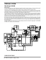
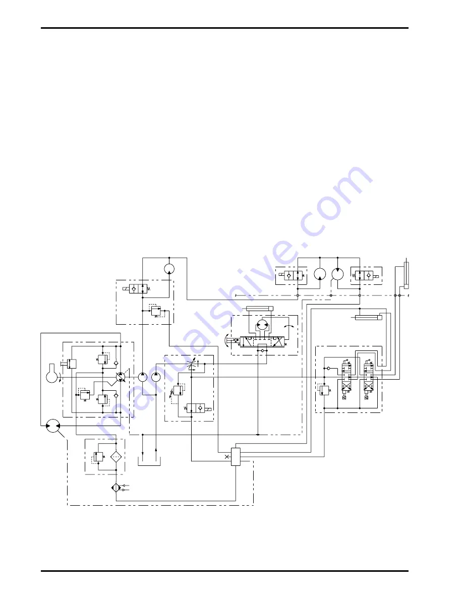
Complete Hydraulic Diagram
OIl Cooler
25 PSI
Return Filter
Hydrostatic 2.49 CIR
Wheel Motor
24.0 CIR
249 RPM
0-9 MPH
S
A
D
Reservoir
11 Gal
SAE 10W30
Ford Engine
1.3L 2400 RPM
Bypass
(Towing)
Valve
B
P
T
Dual
Gear
Pump
8.7
GPM
P
5.2
GPM
1500
PSI
Priority Divider
T
L1
DV
ST
2.0 GPM
T
P
L
R
Steering Unit
4.5 CIR
Steer Cylinder 2 X 6
Hopper
L4
Side
Broom
17.9 CIR
Impeller
.323 CIR
L2
Door Cylinder
1.5 X 4.5
Open
Lift Cylinder
3 X 16.5
A
B
C
D
Dump
Door
Hopper
Lift
2400
PSI
T
Directional Control Valve
A
B
L3
Relief Block
2500
PSI
Main
Broom
4.5 CIR
Manifold
Accessory
Pump
.50
CIR
.84
CIR
B
A
Summary of Contents for Advance Retriever 2060
Page 87: ...4 99 Form No 56040696 page 2 A 3 B C D 5 1 2 6...
Page 94: ...6 99 revised 3 00 Form No 56040702 page 2 5 3 2 6 6 5 3 4 1 2...
Page 111: ...9 00 Form No 56040733 page 2 of 3 Diesel H FRONT M K L N R W P O T S J Q O P U V FIGURE 1...
Page 128: ...PROGRAM PURPOSE and OBJECT ZENITH FUEL SYSTEMS Page 1 1 5 48 7 0 1 2 3 4 5 0 50...
Page 133: ...ZENITH FUEL SYSTEMS Page 5 1 5 0 50 A 50 4 4 B 8 6 A C D FIG 5 1...
Page 134: ...ZENITH FUEL SYSTEMS Page 5 2 6 5 8 0 8 2 0 2 0 2 E F 0 D 50 4 C D 5 5 5 5 6 6 2 0 6 FIG 5 2...
Page 139: ...Fuel Enrichment 4 6 6 50 5 5 6 A 50 5 0 0 ZENITH FUEL SYSTEMS Page 5 7...
Page 144: ...ZENITH FUEL SYSTEMS INC Page 5 12 3F 6 6 H J 3F FIG 5 19 6 G 6 FIG 5 20...
Page 147: ...ZENITH FUEL SYSTEMS Page 6 2 A A 1 6 FIG 6 1...
Page 148: ...ZENITH FUEL SYSTEMS Page 6 3 5 2 3 0 0 1 4 4 B 6 6 6 4 4 3 6 6 6 9 6 6...
Page 149: ...ZENITH FUEL SYSTEMS Page 7 2 8 2...
Page 150: ...ZENITH FUEL SYSTEMS Page 7 3 8 2...
Page 153: ...ZENITH FUEL SYSTEMS Page 9 3...
Page 160: ...ZENITH FUEL SYSTEMS Page 9 11 6 6 9 8 2...
Page 163: ...ZENITH FUEL SYSTEMS Page 9 14 6 6 9 8 Continued...

