54 - FORM NO. 56043051 / Retriever
™
2060
HYDRAULIC SYSTEM
3.25"
(83 mm)
________________________________________________________________________________________________________________________________________________________________________________________________________________________________________________________________________
FUNCTIONAL OVERVIEW
Drive pedal system
The drive pedal has a cable connected to a Hydroback centering assembly that is adjusted to return the forward/reverse drive pedal to
the neutral position. This device uses a heavy spring enclosed in a plastic container to return the pump arm to its center of travel. The
result is no hydraulic oil pumped to the drive motor (neutral) allowing for safe machine operator control.
There is an additional cable that runs from the hopper to a weldment mounted by the propulsion pump arm. When the hopper is raised
the cable will move the actuator weldment, which limits the amount of travel the propulsion pump arm can move. The purpose of this
design is to not allow the machine to be operated at full speed with the hopper in the raised position.
________________________________________________________________________________________________________________________________________________________________________________________________________________________________________________________________________
HYDROBACK AND CABLE ASSEMBLY REPLACEMENT
1
Access cable at foot pedal end by opening right side broom door.
2
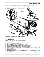
See Figure 7. Remove Cotter Pin (A) and Pin (B) from Clevis (C).
3
Loosen lock nut and remove Clevis (C) from cable.
4
Loosen cable connector Nuts (D) and remove cable from mounting bracket.
5
Pull cable end through opening, toward the rear of the machine.
6
Open the left front service door, lift and move circuit breaker assembly to access the propulsion pump linkage and remove Cotter
Pin (E) and Pin (F) from Clevis (G).
7
Loosen lock nut and remove Clevis (G) and lock nut from cable.
8
Loosen the two connector Nuts (H) and remove Cable (I) and Hydroback (J) from Mount (K).
9
Pull Hydroback and cable assembly through the machine opening. NOTE: If installing a new cable you may want to tape it to pedal
end of the cable and use the old cable to feed the new cable through opening.
10
To separate the Hydroback from the cable, hold Hydroback and unthread the rear swivel fitting from the cable conduit. The
hydroback spring housing can now be unthreaded from the cable end. NOTE: To overcome a housing that may be difficult, double
nut the cable ends to stop the cable from spinning then grip the smaller metal housing with locking pliers and unthread (ccw).
WARNING!
For correct neutral centering operation, install the Hydroback on the output end of the push-pull cable.
11
Install the new Hydroback/cable assembly in reverse order.
CAUTION!
After installing or servicing the Hydroback or drive pedal cable follow the steps in the Hydroback/drive pedal neutral
adjustment section.
________________________________________________________________________________________________________________________________________________________________________________________________________________________________________________________________________
HYDROBACK DRIVE PEDAL NEUTRAL ADJUSTMENT
When servicing the drive system always check for any machine creeping (movement) in the neutral position. The machine must not
move in either forward or reverse after the drive pedal is released. If creeping is experienced the neutral position on the Hydroback must
be adjusted.
WARNING!
Use jack stands to support the machine when setting the neutral adjustment.
1
Block the front wheels. Jack up machine until the rear drive wheel
is off the floor. Place supports under the rear of the machine.
2
Open right side broom access door.
3
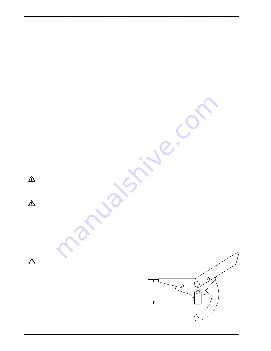
Adjust the two connector Nuts (D) (Figure 7) until the rear of the foot
pedal is 3.25” (83 mm) from the floor plate as shown in figure 6.
4
With the rear wheel off the floor, the machine supported and the front
wheels blocked, start the engine.
FIGURE 6
5
With the foot pedal in the neutral position, see if the drive wheel is moving. Operate the pedal
forward and reverse several times, make sure the pedal returns to neutral and the drive
wheel stops moving.
Summary of Contents for Advance Retriever 2060
Page 87: ...4 99 Form No 56040696 page 2 A 3 B C D 5 1 2 6...
Page 94: ...6 99 revised 3 00 Form No 56040702 page 2 5 3 2 6 6 5 3 4 1 2...
Page 111: ...9 00 Form No 56040733 page 2 of 3 Diesel H FRONT M K L N R W P O T S J Q O P U V FIGURE 1...
Page 128: ...PROGRAM PURPOSE and OBJECT ZENITH FUEL SYSTEMS Page 1 1 5 48 7 0 1 2 3 4 5 0 50...
Page 133: ...ZENITH FUEL SYSTEMS Page 5 1 5 0 50 A 50 4 4 B 8 6 A C D FIG 5 1...
Page 134: ...ZENITH FUEL SYSTEMS Page 5 2 6 5 8 0 8 2 0 2 0 2 E F 0 D 50 4 C D 5 5 5 5 6 6 2 0 6 FIG 5 2...
Page 139: ...Fuel Enrichment 4 6 6 50 5 5 6 A 50 5 0 0 ZENITH FUEL SYSTEMS Page 5 7...
Page 144: ...ZENITH FUEL SYSTEMS INC Page 5 12 3F 6 6 H J 3F FIG 5 19 6 G 6 FIG 5 20...
Page 147: ...ZENITH FUEL SYSTEMS Page 6 2 A A 1 6 FIG 6 1...
Page 148: ...ZENITH FUEL SYSTEMS Page 6 3 5 2 3 0 0 1 4 4 B 6 6 6 4 4 3 6 6 6 9 6 6...
Page 149: ...ZENITH FUEL SYSTEMS Page 7 2 8 2...
Page 150: ...ZENITH FUEL SYSTEMS Page 7 3 8 2...
Page 153: ...ZENITH FUEL SYSTEMS Page 9 3...
Page 160: ...ZENITH FUEL SYSTEMS Page 9 11 6 6 9 8 2...
Page 163: ...ZENITH FUEL SYSTEMS Page 9 14 6 6 9 8 Continued...

