5/99 revised 7/01 Form No. 56040692
(page 3 of 6)
17
29
16
20
18
10
7
E
F
7
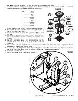
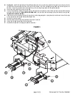
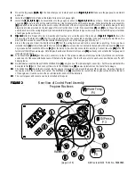
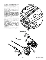
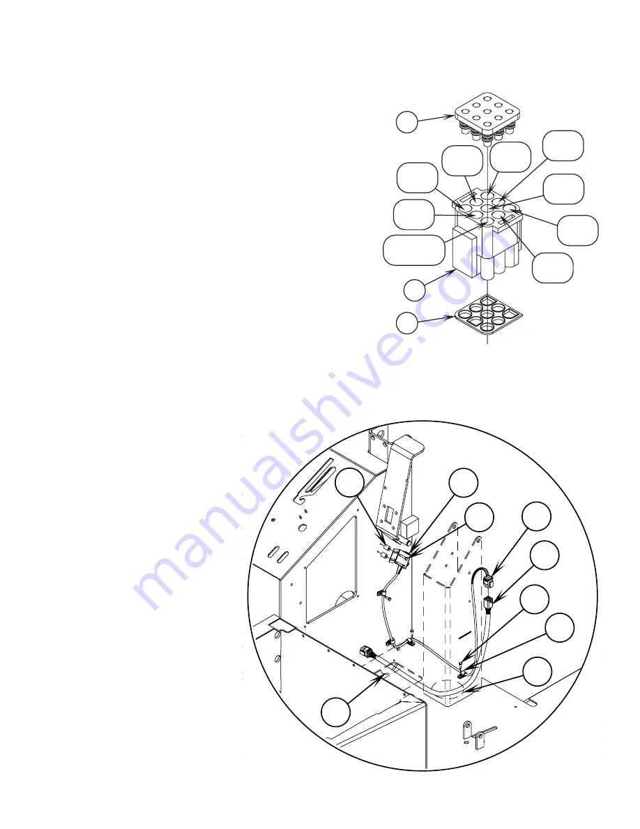
See Figure 2.
Insert Seal
(11)
into the top of Connector
(7)
and Seal
(12)
onto the bottom as shown.
8
Insert the wires from the Turn Signal Assembly
(1)
into the top of the Connector
(7)
as shown (see chart below). The two wires from the
Waterproof Switch
(17)
are inserted into port 8 and 9 of the Connector
(7)
.
PORT
WIRE
1 ..................... YELLOW
2 ........................ BLUE
3 ......................... RED
4 ....................... BLACK
5 ...................... GREEN
6 ........................ GRAY
7 ................. BLACK/GRAY
8 ....................... BLACK
9 ....................... WHITE
9
Drop the Waterproof Switch
(17)
down through the steering column housing.
11
7
12
1
YEL
2
BLU
3
RED
4
BLK
6
GRA
7
BLK/GRA
8
BLK
9
WHT
5
GRN
FIGURE 2
10
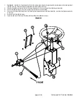
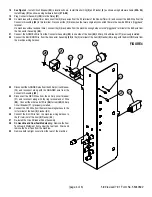
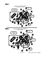
See Figure 3.
Mount the Switch
(17)
to the side panel using the (2) Bushings
(16)
and the (2) Screws
(29)
as shown.
11
Route the wires as shown and secure with the (4) Cord Clamps
(20)
using the (4)
Screws
(18)
.
12
Adjust the Switch
(17)
so that it closes when you step on the brake pedal (it is a
normally closed switch and should be activated open when the brake pedal is
released).
13
Plug the Turn Signal Switch Harness
(10)
into the Connector
(7)
and route down
though the steering column housing and through Opening
(E)
in floorboard di-
rectly below.
14
Remove the horn switch plate from the floorboard to allow access underneath to route the Harness
(10)
past and through Opening
(F)
in side
panel into battery compartment as shown in Figure 3.
15
In the area where the Turn Signal Switch Harness
(10)
comes through the side panel, there is an unused connector in the main wiring harness.
Plug the Turn Signal Switch Harness
(10)
into this connector. Use Cable Ties
(8)
where needed to secure wires.
16
Re-install the horn switch plate.
17
Remove the Circuit Breaker Panel Assembly from the machine.
FIGURE 3
Summary of Contents for Advance Retriever 2060
Page 87: ...4 99 Form No 56040696 page 2 A 3 B C D 5 1 2 6...
Page 94: ...6 99 revised 3 00 Form No 56040702 page 2 5 3 2 6 6 5 3 4 1 2...
Page 111: ...9 00 Form No 56040733 page 2 of 3 Diesel H FRONT M K L N R W P O T S J Q O P U V FIGURE 1...
Page 128: ...PROGRAM PURPOSE and OBJECT ZENITH FUEL SYSTEMS Page 1 1 5 48 7 0 1 2 3 4 5 0 50...
Page 133: ...ZENITH FUEL SYSTEMS Page 5 1 5 0 50 A 50 4 4 B 8 6 A C D FIG 5 1...
Page 134: ...ZENITH FUEL SYSTEMS Page 5 2 6 5 8 0 8 2 0 2 0 2 E F 0 D 50 4 C D 5 5 5 5 6 6 2 0 6 FIG 5 2...
Page 139: ...Fuel Enrichment 4 6 6 50 5 5 6 A 50 5 0 0 ZENITH FUEL SYSTEMS Page 5 7...
Page 144: ...ZENITH FUEL SYSTEMS INC Page 5 12 3F 6 6 H J 3F FIG 5 19 6 G 6 FIG 5 20...
Page 147: ...ZENITH FUEL SYSTEMS Page 6 2 A A 1 6 FIG 6 1...
Page 148: ...ZENITH FUEL SYSTEMS Page 6 3 5 2 3 0 0 1 4 4 B 6 6 6 4 4 3 6 6 6 9 6 6...
Page 149: ...ZENITH FUEL SYSTEMS Page 7 2 8 2...
Page 150: ...ZENITH FUEL SYSTEMS Page 7 3 8 2...
Page 153: ...ZENITH FUEL SYSTEMS Page 9 3...
Page 160: ...ZENITH FUEL SYSTEMS Page 9 11 6 6 9 8 2...
Page 163: ...ZENITH FUEL SYSTEMS Page 9 14 6 6 9 8 Continued...

