5/99 revised 7/01 Form No. 56040692
(page 4 of 6)
18
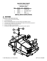
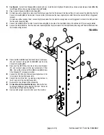
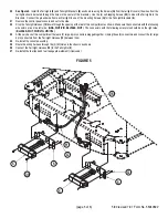
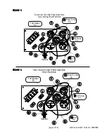
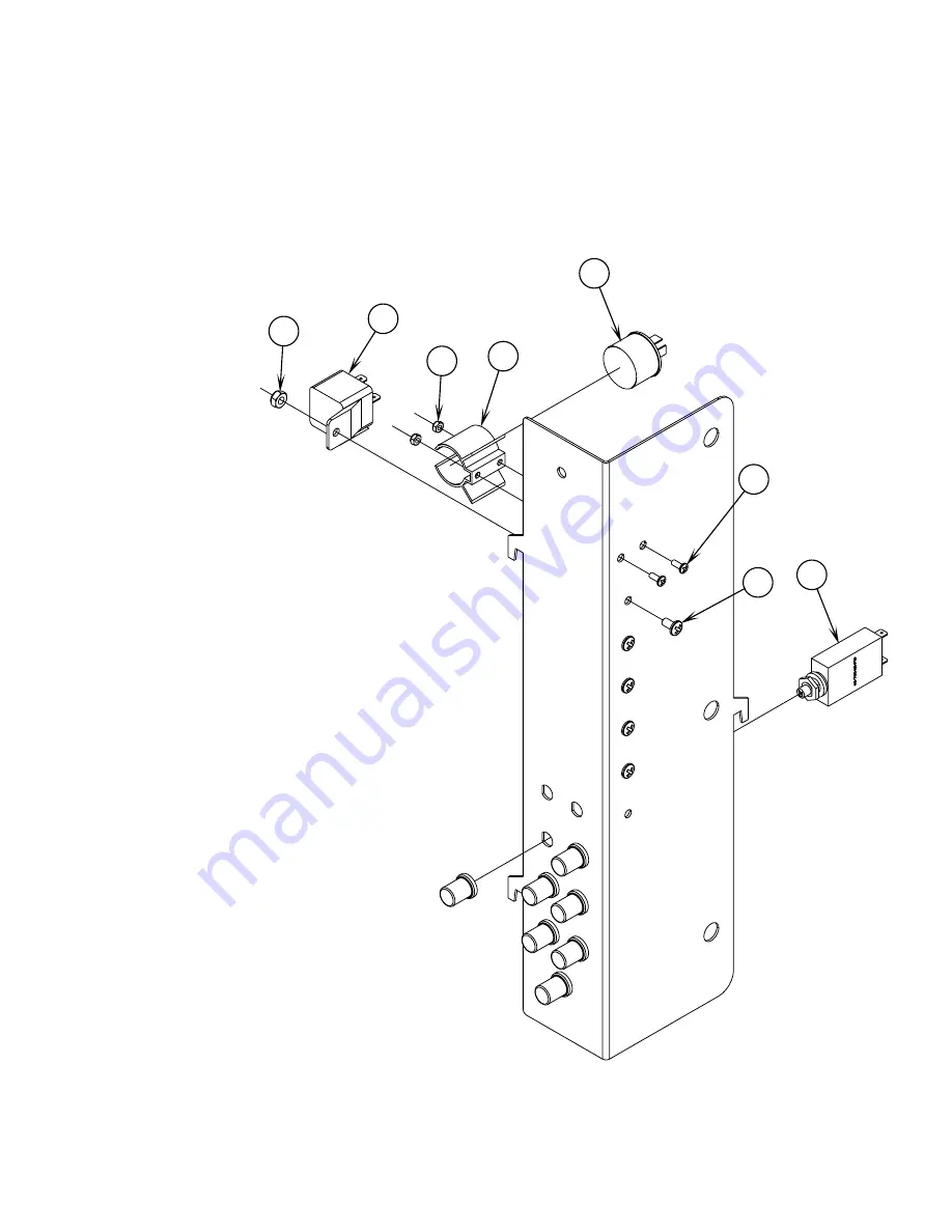
See Figure 4.
Install Circuit Breaker
(22)
in location shown. Install Flasher Clip
(3)
and Flasher
(2)
as shown using hardware items
(23 & 24)
.
Install Relay
(21)
as shown using hardware items
(27 & 28)
.
19
Plug Connector Assembly
(25)
into the Relay
(21)
.
20
On machines with a shaker timer, disconnect the (2) black wires from the #3 terminal of the Shaker Timer (E) and connect the BLK Wire from the
Connector Assembly
(25)
to this terminal. Reconnect the (2) black wires that were originally connected there to the new BLK Wire’s “piggyback”
terminal.
On machines without a shaker timer, connect the (2) black wires from the machine wiring harness to the “piggyback” terminal of the BLK wire from
the Connector Assembly
(25)
.
21
Connect the GRN/YEL Wire from the Connector Assembly
(25)
to one side of the item
(22)
20 Amp Circuit Breaker (F7) previously installed.
22
Connect the BLU/ORN Wire . from the Connector Assembly
(25)
to the (X) terminal of the item
(2)
Flasher (E2) along with the BLU/ORN wire from
the machine wiring harness.
22
2
3
23
24
21
27
28
23
Disconnect the GRA/RED wire from the 20 Amp circuit breaker
(F4) and reconnect along with the GRA/RED wire from the
Connector Assembly
(25)
.
24
Disconnect the RED Wires from the 40 Amp circuit breaker
(F1) and reconnect along with the ring terminal end of Wire
(26)
. Connect the other end of Wire
(26)
to item
(22)
20 Amp
Circuit Breaker (F7) previously installed.
25
Connect the YEL Wire from the machine wiring harness to the
(L) terminal of the item
(2)
Flasher (E2).
26
Connect the BLU Wire from the machine wiring harness to
the (P) terminal of the item
(2)
Flasher (E2).
27
Re-install the Circuit Breaker Panel Assembly.
28
On Gasoline and Dual Fuel Models only:
Remove the Fuel
Tank Guard Weldment from under the fuel tank. Drain and
remove the Fuel Tank from the machine.
29
Remove both tail light covers from the rear of the machine.
FIGURE 4
Summary of Contents for Advance Retriever 2060
Page 87: ...4 99 Form No 56040696 page 2 A 3 B C D 5 1 2 6...
Page 94: ...6 99 revised 3 00 Form No 56040702 page 2 5 3 2 6 6 5 3 4 1 2...
Page 111: ...9 00 Form No 56040733 page 2 of 3 Diesel H FRONT M K L N R W P O T S J Q O P U V FIGURE 1...
Page 128: ...PROGRAM PURPOSE and OBJECT ZENITH FUEL SYSTEMS Page 1 1 5 48 7 0 1 2 3 4 5 0 50...
Page 133: ...ZENITH FUEL SYSTEMS Page 5 1 5 0 50 A 50 4 4 B 8 6 A C D FIG 5 1...
Page 134: ...ZENITH FUEL SYSTEMS Page 5 2 6 5 8 0 8 2 0 2 0 2 E F 0 D 50 4 C D 5 5 5 5 6 6 2 0 6 FIG 5 2...
Page 139: ...Fuel Enrichment 4 6 6 50 5 5 6 A 50 5 0 0 ZENITH FUEL SYSTEMS Page 5 7...
Page 144: ...ZENITH FUEL SYSTEMS INC Page 5 12 3F 6 6 H J 3F FIG 5 19 6 G 6 FIG 5 20...
Page 147: ...ZENITH FUEL SYSTEMS Page 6 2 A A 1 6 FIG 6 1...
Page 148: ...ZENITH FUEL SYSTEMS Page 6 3 5 2 3 0 0 1 4 4 B 6 6 6 4 4 3 6 6 6 9 6 6...
Page 149: ...ZENITH FUEL SYSTEMS Page 7 2 8 2...
Page 150: ...ZENITH FUEL SYSTEMS Page 7 3 8 2...
Page 153: ...ZENITH FUEL SYSTEMS Page 9 3...
Page 160: ...ZENITH FUEL SYSTEMS Page 9 11 6 6 9 8 2...
Page 163: ...ZENITH FUEL SYSTEMS Page 9 14 6 6 9 8 Continued...

