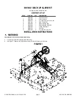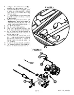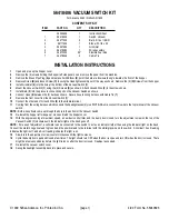
4/99 Form No. 56040696
© 1999 Nilfisk-Advance, Inc. Printed in USA
(page 1)
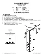
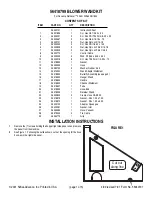
56418406 VACUUM SWITCH KIT
For Advance 2060 / Nilfisk SR 1800
CONTENTS OF KIT
ITEM
PART NO.
QTY
DESCRIPTION
56040696
1
Instruction Sheet
1
56418404
1
Switch, Vacuum
2
56477522
2
Barb, 3/16 x 1/8 BR
3
56111309
1
Elbow St. 1/8 x 90
4
56057434
1
Grommet
5
56418380
1
Wire Assembly
6
56370002
35”
Flexible Fuel Line
7
56478246
4
Cable Tie
INSTALLATION INSTRUCTIONS
1
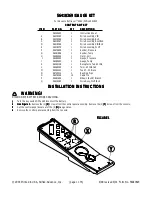
Open and prop up the hopper cover.
2
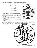
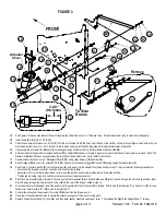
Remove the (6) screws holding the hopper left side panel on and remove the panel from the machine.
3
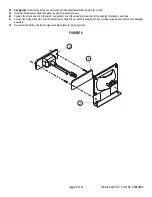
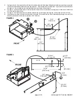
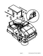
Remove the Brass Pipe Plug
(A)
and replace it with Elbow
(3)
, point the barb at a downward angle towards the front of the hopper.
4
Remove Screw
(B)
and loosen Screw
(C)
to swing the Headlight assembly out of the way as shown. Remove the (2)
(D)
Screws from the hopper.
5
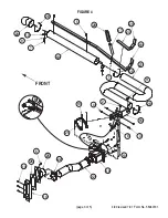
Install Grommet
(4)
into the hole at the bottom of the Vacuum Switch
(1)
.
6
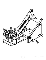
Mount the Vacuum Switch
(1)
using the (2) Screws
(D)
as shown. Attach Ground Wire
(5)
to the screw shown.
7
Install Barb
(2)
into the pressure connection port on the Vacuum Switch as shown.
8
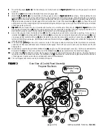
Connect Hose
(6)
between the (2) barbs as shown. Secure hose to wiring harness with Cable Tie
(7)
.
9
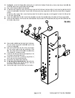
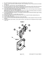
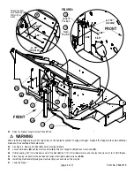
Remove the front cover from the Vacuum Switch
(1)
.
10
Connect the other end of Ground Wire
(5)
to the middle terminal.
11
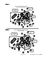
Coming from the wiring harness which connects the headlight assembly is a WHT/GRA wire, connect this wire to the top terminal of the Vacuum
switch.
NOTE:
Both wires should come up through the hole in the bottom of the Vacuum Switch.
13
Re-install the hopper left side panel , close and latch the hopper cover.
14
With the engine running at maximum speed, a new dust control filter, and the dump door closed, turn the adjustment screw on the top of the
Vacuum Switch
(1)
clockwise until the indicator light on the dash goes off.
NOTE:
For ease of adjustment, a voltmeter can be connected to the switch to act as an indicator rather than using the indicator light on the dash.
Connect the meter’s negative lead to ground and the positive lead to the terminal with the white/gray wire on the switch. A nominal 12-volt reading
indicates the light is off, and a 0-volt reading indicates the light is on.
15
Slowly turn the adjustment screw counter clockwise until the light comes on.
16
Cycle the dump door open and closed a few times. The light should turn OFF when the door is open and turn ON when the door is closed. There
might be a few second delay before the light turns on after the door is closed. Readjust as needed.
17
Re-install the vacuum switch cover.
18
Swing the headlight assembly back into place and secure.
Summary of Contents for Advance Retriever 2060
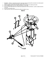
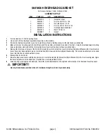
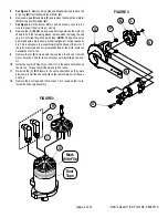
Page 87: ...4 99 Form No 56040696 page 2 A 3 B C D 5 1 2 6...
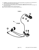
Page 94: ...6 99 revised 3 00 Form No 56040702 page 2 5 3 2 6 6 5 3 4 1 2...
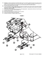
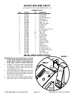
Page 111: ...9 00 Form No 56040733 page 2 of 3 Diesel H FRONT M K L N R W P O T S J Q O P U V FIGURE 1...
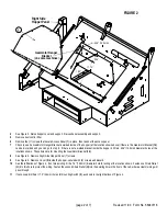
Page 128: ...PROGRAM PURPOSE and OBJECT ZENITH FUEL SYSTEMS Page 1 1 5 48 7 0 1 2 3 4 5 0 50...
Page 133: ...ZENITH FUEL SYSTEMS Page 5 1 5 0 50 A 50 4 4 B 8 6 A C D FIG 5 1...
Page 134: ...ZENITH FUEL SYSTEMS Page 5 2 6 5 8 0 8 2 0 2 0 2 E F 0 D 50 4 C D 5 5 5 5 6 6 2 0 6 FIG 5 2...
Page 139: ...Fuel Enrichment 4 6 6 50 5 5 6 A 50 5 0 0 ZENITH FUEL SYSTEMS Page 5 7...
Page 144: ...ZENITH FUEL SYSTEMS INC Page 5 12 3F 6 6 H J 3F FIG 5 19 6 G 6 FIG 5 20...
Page 147: ...ZENITH FUEL SYSTEMS Page 6 2 A A 1 6 FIG 6 1...
Page 148: ...ZENITH FUEL SYSTEMS Page 6 3 5 2 3 0 0 1 4 4 B 6 6 6 4 4 3 6 6 6 9 6 6...
Page 149: ...ZENITH FUEL SYSTEMS Page 7 2 8 2...
Page 150: ...ZENITH FUEL SYSTEMS Page 7 3 8 2...
Page 153: ...ZENITH FUEL SYSTEMS Page 9 3...
Page 160: ...ZENITH FUEL SYSTEMS Page 9 11 6 6 9 8 2...
Page 163: ...ZENITH FUEL SYSTEMS Page 9 14 6 6 9 8 Continued...

