4/99 revised 7/01 Form No. 56040701
(page 4 of 5)
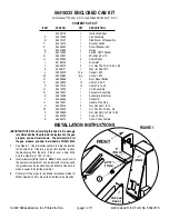
FRONT
6
25
26
14
10
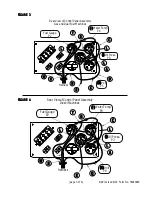
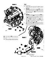
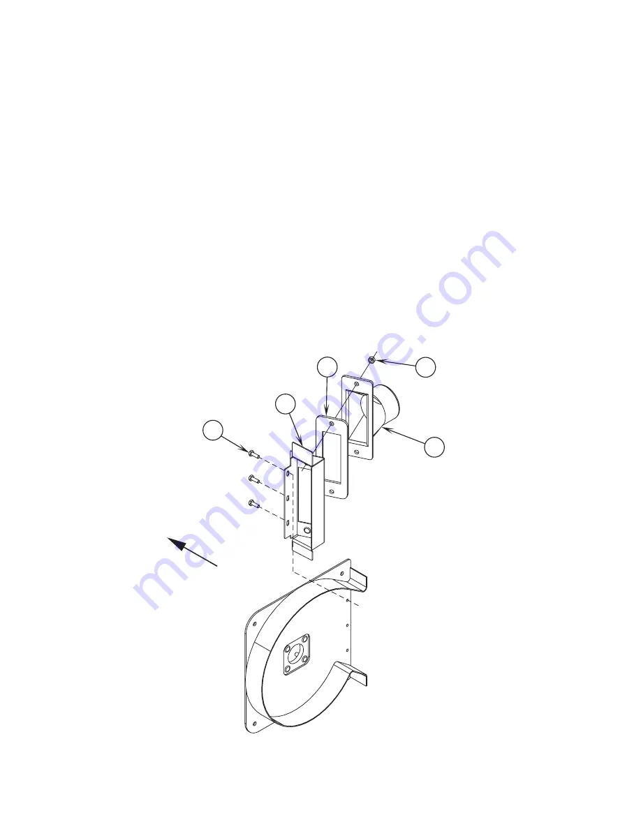
FIGURE 5
7
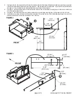
Mount Wand Retainer
(21)
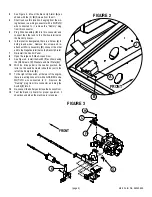
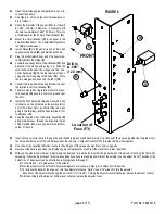
to the right side bumper using (2) of the (8) item
(10)
Screws as shown in Figure 2.
8
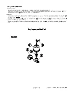
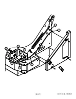
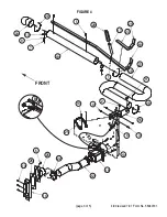
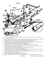
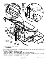
See Figure 4. Place the Gasket
(11)
onto the Wand Hanger
(16)
. Mount the Wand Hanger on the rear of the hopper assembly with hardware
items
(3)
and
(4)
.
9
If not already done, assemble items
(1, 5, 7, 9, 13, 17-20, 23, 24, 27-29)
as shown.
10
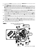
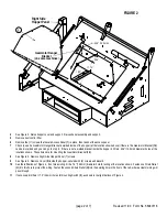
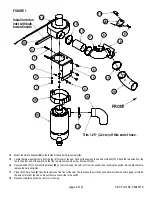
Open and prop-up the Hopper Cover. Open and prop-up the Shaker Assembly and remove the Dust Control Filter from the machine. Remove the
panel directly behind the dust control filter. If the dump door cylinder fittings are facing to rear of machine, cylinder must be turned 180
º
.
11
Install the Butterfly Assembly
(15)
as shown using (3) of the (8) item
(10)
Screws.
12
Install the Control Cable
(8)
to the Wand Hanger
(16)
using the (2) item
(2)
Screws as shown. Route the cable through the Round Hole
(A)
below
it’s mounting location and connect to the Butterfly Assembly
(15)
.
NOTE:
Make sure the T-Handle of the Control Cable
(8)
is all the way RIGHT and the Arm
(B)
on the Butterfly Assembly
(15)
is turned all the way
Clock-Wise before tightening the set screw which holds the cable in place as shown in Figure 2.
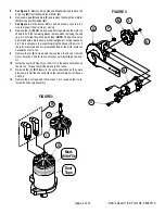
13
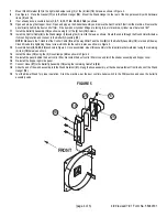
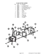
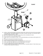
Assemble items
(6, 14, 25, 26)
as shown in Figure 5. Once assembled, mount this assembly to the impeller bracket weldment using the remaining
(3) item
(10)
Screws as shown.
14
Install the Hose
(12)
using the (2) Hose Clamps
(22)
as shown in Figure 4.
15
Re-install the panel behind the dust control filter. Re-install the dust control filter, close and latch the shaker assembly and hopper cover.
16
Re-install the hopper right side panel.
17
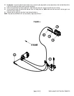
Connect Hose
(27)
to the Butterfly Assembly
(15)
using the remaining Cable Tie
(28)
.
18
Slide the end of the wand assembly into the Wand Retainer
(21)
. Hang the hose assembly, at the channel weldment from the hook of the Wand
Hanger
(16)
.
19
Test the Blower Wand for proper operation. Start the machine, put the dust control shaker switch in the FAN position and open the butterfly
assembly valve.
Summary of Contents for Advance Retriever 2060
Page 87: ...4 99 Form No 56040696 page 2 A 3 B C D 5 1 2 6...
Page 94: ...6 99 revised 3 00 Form No 56040702 page 2 5 3 2 6 6 5 3 4 1 2...
Page 111: ...9 00 Form No 56040733 page 2 of 3 Diesel H FRONT M K L N R W P O T S J Q O P U V FIGURE 1...
Page 128: ...PROGRAM PURPOSE and OBJECT ZENITH FUEL SYSTEMS Page 1 1 5 48 7 0 1 2 3 4 5 0 50...
Page 133: ...ZENITH FUEL SYSTEMS Page 5 1 5 0 50 A 50 4 4 B 8 6 A C D FIG 5 1...
Page 134: ...ZENITH FUEL SYSTEMS Page 5 2 6 5 8 0 8 2 0 2 0 2 E F 0 D 50 4 C D 5 5 5 5 6 6 2 0 6 FIG 5 2...
Page 139: ...Fuel Enrichment 4 6 6 50 5 5 6 A 50 5 0 0 ZENITH FUEL SYSTEMS Page 5 7...
Page 144: ...ZENITH FUEL SYSTEMS INC Page 5 12 3F 6 6 H J 3F FIG 5 19 6 G 6 FIG 5 20...
Page 147: ...ZENITH FUEL SYSTEMS Page 6 2 A A 1 6 FIG 6 1...
Page 148: ...ZENITH FUEL SYSTEMS Page 6 3 5 2 3 0 0 1 4 4 B 6 6 6 4 4 3 6 6 6 9 6 6...
Page 149: ...ZENITH FUEL SYSTEMS Page 7 2 8 2...
Page 150: ...ZENITH FUEL SYSTEMS Page 7 3 8 2...
Page 153: ...ZENITH FUEL SYSTEMS Page 9 3...
Page 160: ...ZENITH FUEL SYSTEMS Page 9 11 6 6 9 8 2...
Page 163: ...ZENITH FUEL SYSTEMS Page 9 14 6 6 9 8 Continued...

