SOLUTION SYSTEM
63
Service Manual – Advenger, 2800ST, 3800ST, BR 755, BR 855
Solution System Control
Advenger / BR 755, 855
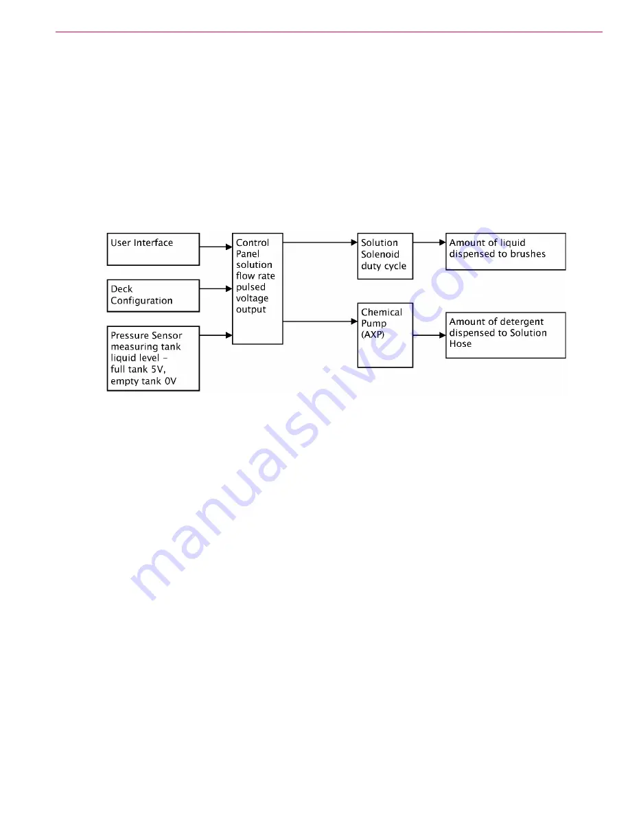
The control board output of pulsed voltage signals driving the Solution System is controlled by the following three parameters:
1 The deck size and type (factory set but selectable via Hidden Menu).
2 The Solution Flow Rate chosen by the operator through the user interface.
3 The Liquid Level Sensor.
The liquid level in the Solution Tank is measured by the Pressure Sensor through the Pressure Sensing Tube. As the liquid level decreases,
the pulsed feedback of the Pressure Sensor drives the control board to compensate for this drop in maximum output by adjusting the duty
cycle of the solution solenoid, thereby keeping the flow rate constant.
FIGURE 29
A malfunction of either the Pressure Sensor, the Control Panel, or an air leak in the pressure sensing system may affect the performance of
either the Chemical Pump or the Solution Solenoid, or both.
ST
The pulsed 24V output of the control board that controls duty cycle of the Solution Solenoid is driven by:
1 Control board programming of deck size and type (factory set but selectable via the Hidden Menu).
2 The Solution Flow Rate chosen by the operator through the user interface.
ST machines don’t have a Pressure Sensor that monitors liquid level in the Solution Tank. Since the maximum output of the Solution Solenoid
varies with liquid level, as the level drops in the tank, the output of the Solution Solenoid will also drop. As the tank empties, this results in a
decrease in solution output to the brushes from the “full” rate.


