20
- FORM NO. 56043025 / BA 700, 800, 1000 / 28LX, 32LX, 38LX / 280HD, 320HD, 380HD
BRUSH DRIVE SYSTEM
F
FRONT
E
E
E
FRONT
F
E
4
Loosen the
(B)
Bolts and Nuts.
5
Loosen the
(C)
Lock Nuts and turn the
(D)
Bolts to adjust the belt tension. There should be about 3/32 inch (2 mm)
of belt deflection when 3-1/4 pounds of pressure is applied between the pulleys.
6
Follow steps 1-5 in reverse order to reassemble.
7
After the adjustment is complete, test to make sure the belt does not slip.
_____________________________________________________________________________
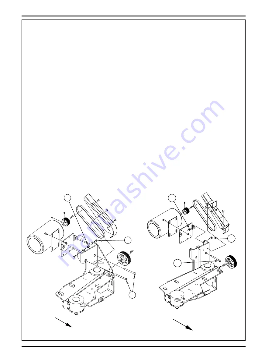
BELT TENSION ADJUSTMENT - BA 800, 1000 / 32, 38LX / 320, 380HD
1
Drain and tip the solution tank to the side of the machine.
2
See Figure 2. Loosen the
(E)
Bolts and Nuts.
3
Loosen the lock nuts and turn the
(F)
Bolts to adjust the belt tension. There should be about 3/32 inch (2 mm) of belt
deflection when 3-1/4 pounds of pressure is applied between the pulleys.
4
After the adjustment is complete, test to make sure the belt does not slip.
_____________________________________________________________________________________________________________________________
BELT TENSION ADJUSTMENT - BA 700 / 28LX / 280HD (continued)
FIGURE 2
BA 800 / 32LX / 320HD
BA 1000 / 38LX / 380HD


