background image

3707/10 - 3907 - 3907/18 

GB

C340

14

04/2009

Wiring diagrams

Basic machine (1/3)

Figure 18

1. 

MAIN DISCONNECTOR

2. 

INVERTER

3. 

THREEPOLAR FUSING HOLDER

4. 

THERMAL RELAY

5.  VACUUM
6. 

FUSING HOLDER TRANSFORMER

Model

Fuse type "F1"

3707

3 x 25 A

3707/10

3 x 35 A

3907-3907W

3 x 50 A

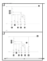
Basic machine (2/3)

Figure 19

1. 

TRANSFORMER

2. 

VOLTAGE INDICATOR

3. 

VOLTAGE INDICATOR

4.  RED LAMP
5.  WHITE LAMP

Basic machine (3/3)

Figure 20

1.  STOP PULSE
2.  START PULSE
3. 

LINE CONTACTOR

4. 

HOURS COUNTER

5.  STAR-DELTA TIMER
6. 

STAR CONTACTOR

7. 

DELTA CONTACTOR

8.  WIRE UP WITH A 1 mm

2

 RED WIRE WHERE NOT 

SPECIFIED.

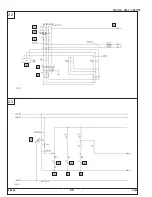
Electric filter shaker (1/1)

Figure 21

1.  STOP PULSE
2.  START PULSE
3. 

LINE CONTACTOR

4. 

HOURS COUNTER

5.  STAR-DELTA TIMER
6. 

STAR CONTACTOR

7. 

DELTA CONTACTOR

8. 

FILTER SHAKER CONTACTOR

9.  FILTER SHAKER PULSE
10.  WIRE UP WITH A 1 mm

2

 RED WIRE WHERE NOT 

SPECIFIED.

Phase sequence (1/3)

Figure 22

1. 

MAIN DISCONNECTOR

2. 

INVERTER

3. 

THREEPOLAR FUSING HOLDER

4. 

PHASE SEQUENCE RELAY

5. 

THERMAL RELAY

6.  VACUUM
7. 

FUSING HOLDER TRANSFORMER

Model

Fuse type "F1"

3707

3 x 25 A

3707/10

3 x 35 A

3907-3907W

3 x 50 A

Phase sequence (2/3)

Figure 23

1. 

TRANSFORMER

2. 

VOLTAGE INDICATOR

3. 

THERMAL INDICATOR

4. 

PHASE SEQUENCE INDICATOR

5. 

YELLOW LAMP

6.  RED LAMP
7.  WHITE LAMP

Phase sequence (3/3)

Figure 24

1.  STOP PULSE
2.  START PULSE
3. 

LINE CONTACTOR

4. 

HOURS COUNTER

5.  STAR-DELTA TIMER
6. 

STAR CONTACTOR

7. 

DELTA CONTACTOR

8.  WIRE UP WITH A 1 mm

2

 RED WIRE WHERE NOT 

SPECIFIED.

Cartridge kit (1/1)

Figure 25

1. 

TS2 TIMER SEQUENCE

2. 

FILTER 1 CLEAN ELECTROVALVE

3. 

FILTER 2 CLEAN ELECTROVALVE

4. 

FILTER 3 CLEAN ELECTROVALVE

5. 

FILTER 4 CLEAN ELECTROVALVE

6. 

T3 / P2 = TIME IN THE MIDDLE OF CLEANING CYCLES

7. 

T1 / WORK = FILTER CLEANING TIME

8.  T2 / P1 = WORK HOLD TIME

Summary of Contents for CFM 3707/10

Page 1: ...Instructions for Use Manual Nilfisk CFM 3707 10 Nilfisk CFM 3907 Nilfisk CFM 3907 18 4 2009 C340 ...

Page 2: ......

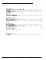
Page 3: ...ta Dimensions 9 Controls indicators and connections 10 Inspections prior to starting 10 Starting up 10 Operating the vacuum 10 Cleaning the main filter 10 Emergency stopping 11 Emptying the container 11 At the end of a cleaning session 11 Maintenance cleaning and decontamination 12 How to disassemble and replace the main and Hepa filters 12 Main filter replacement 12 Hepa Ulpa filter replacement 1...

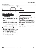
Page 4: ...rs must be informed instructed and trained on how to work it and for which substances its usage is permitted including the safe method for removing and disposing of the vacuumed material To reduce the risk of fire electric shock or injury Do not leave appliance when plugged in Unplug from outlet when not in use and before servicing To reduce the risk of electrical shock do not use outdoors or on w...

Page 5: ... dusts etc The vacuum cleaner is not suitable for vacuuming explosive or similar substances as established by the laws governing explosive substances particularly liquid fuels and mixtures of flammable dusts and liquids WARNING Emergency If an emergency situation occurs filter breakage fire outbreak short circuit motor block electric shock etc turn off the vacuum cleaner unplug it and ask for assi...

Page 6: ...he panel is powered by the voltage given on the data plate N Attention plate voltage Only authorized personnel should be allowed access to the electrical control panel The electrical components must only be accessed after the power supply has been disconnected by setting main switch D to position 0 off and after having removed the plug from the current socket This vacuum cleaner creates a strong a...

Page 7: ...ble does not show signs of damage excessive wear cracks or ageing WARNING When the vacuum cleaner is operating do not Crush pull damage or tread on the cable that connects to the power supply Only disconnect the cable from the power supply by removing the plug do not pull the cable Only replace the electric power cable with the same type as the original The same rule applies if an extension is use...

Page 8: ...foam or liquid leaks out Regularly clean the liquid level limiting device and check to make sure that there are no signs of damage The dirty liquid collected by the vacuum must be considered conductive Maintenance and repairs WARNING Disconnect the vacuum cleaner from its power source before cleaning servicing replacing parts or converting it to obtain another version variant The plug must be remo...

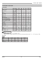
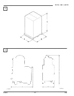
Page 9: ...oise Level 3 3 1 meter dB A 78 78 78 Protection IP 55 55 55 Insulation Class F F F Tank Capacity gallons 46 46 46 Machine Inlet inches 4 4 4 Dimensions l x w x h inches 65 x 32 7 x 70 9 65 x 32 7 x 70 9 65 x 32 7 x 70 9 Weight lbs 682 794 792 Cord Length ft 30 30 30 Filter Efficiency HEPA DOP tested 99 995 0 18 microns 99 995 0 18 microns 99 995 0 18 microns Note 1 Storage conditions T 10 40 C Hum...

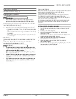
Page 10: ...ck the flow rate When the vacuum cleaner is operating the pointer of the vacuum gauge A Fig 7 must remain in the green zone OK to ensure that the speed of the intake air does not drop below the safety value of 20 m s If the pointer is in the red zone STOP it means that the speed of the air in the hose is below 20 m s and that the vacuum cleaner is not working safely Clean or replace the filters Wh...

Page 11: ...and or hazardous for the health must be removed The container and or liner must only be disposed of by trained personnel and in compliance with the current laws in force Use as a wet cleaner Make sure that the vacuum cleaner is equipped with a float liquid level sensor and is suitable for use as a wet cleaner Do not clean up flammable liquids If foam forms stop work immediately and empty the conta...

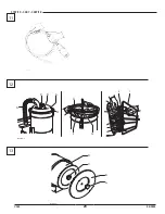
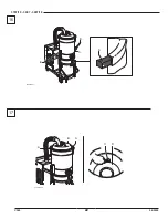
Page 12: ...ectric control panel operates correctly This inspection must be carried out by the manufacturer or by a qualified person WARNING Only use genuine spare parts How to disassemble and replace the main and Hepa filters WARNING When the vacuum cleaner is used to clean up hazardous substances the filters become contaminated thus work with care and avoid spilling the vacuumed dust and or material place t...

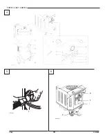
Page 13: ...um seal cannot be obtained Checking the seal of filter chamber If seal A Fig 16 between the container and filter chamber C fails to secure loosen the four screws B Fig 16 that lock filter chamber C against vacuum structure Allow filter chamber C Fig 16 to lower down and relock screws B once it has reached the retention position The seal must be replaced if it is torn cut etc Replace seal A Fig 16 ...

Page 14: ...R CONTACTOR 9 FILTER SHAKER PULSE 10 WIRE UP WITH A 1 mm2 RED WIRE WHERE NOT SPECIFIED Phase sequence 1 3 Figure 22 1 MAIN DISCONNECTOR 2 INVERTER 3 THREEPOLAR FUSING HOLDER 4 PHASE SEQUENCE RELAY 5 THERMAL RELAY 6 VACUUM 7 FUSING HOLDER TRANSFORMER Model Fuse type F1 3707 3 x 25 A 3707 10 3 x 35 A 3907 3907W 3 x 50 A Phase sequence 2 3 Figure 23 1 TRANSFORMER 2 VOLTAGE INDICATOR 3 THERMAL INDICAT...

Page 15: ...medies The vacuum suddenly stops Clogged main filter Shake the filter Replace it if this is not sufficient Clogged suction hose Check the suction hose and clean it Motor protector tripper Check the setting Check the power draw of the motor Contact an authorized after sales service center if necessary Dust leaks from the vacuum The filter is torn Change it with another of identical category Inadequ...

Page 16: ...3707 10 3907 3907 18 GB C340 16 04 2009 1 ...

Page 17: ...3707 10 3907 3907 18 04 2009 17 C340 3707LMH11 3707LMH12 A B C 2 3 ...

Page 18: ...3707 10 3907 3907 18 GB C340 18 04 2009 F 3307LMH11 3707LMH03 F B I E 4 5 6 ...

Page 19: ...3707 10 3907 3907 18 04 2009 19 C340 A 3307LMH13 1 2 J 3307LMH14 3307LMH15 I I 3707LMH07 7 8 9 10 ...

Page 20: ...3707 10 3907 3907 18 GB C340 20 04 2009 3307LMH18 I L H F G A C B E D 11 12 13 3307LMH20 D C B A ...

Page 21: ...3707 10 3907 3907 18 04 2009 21 C340 3707LMH04 B A C 3307LMH22 B D C 14 15 ...

Page 22: ...3707 10 3907 3907 18 GB C340 22 04 2009 3307LMH23 B A C B 3707LMH05 D A C B A 17 16 ...

Page 23: ...3707 10 3907 3907 18 04 2009 23 C340 18 19 1 2 3 4 5 6 1 2 3 4 5 ...

Page 24: ...3707 10 3907 3907 18 GB C340 24 04 2009 21 20 1 2 5 6 7 8 3 4 5 6 7 8 1 2 3 4 9 10 ...

Page 25: ...3707 10 3907 3907 18 04 2009 25 C340 23 22 5 6 7 1 2 3 4 5 6 7 1 2 3 4 ...

Page 26: ...3707 10 3907 3907 18 GB C340 26 04 2009 25 24 5 6 7 8 1 2 3 4 5 6 7 8 1 2 3 4 ...

Page 27: ...3707 10 3907 3907 18 04 2009 27 C340 26 ...

Page 28: ......

Reviews: