30 - 56043021
- 260, 32, 38, 320, 380
BRUSH DRIVE SYSTEM
4
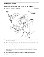
See Figure 13. Loosen the (2) “KK” lock nuts.
5
Turn the left adjustment shaft “LL” until the control handle lock “MM” will drop easily into the notch “NN”
without moving the left handle.
6
After the left handle is adjusted and locked in neutral, adjust the right shaft until the (2) handles line up
and can be pinned together easily.
7
After the adjustment is complete, tighten the (2) “KK” lock nuts.
8
Test run the machine to make sure it does not move in any direction when locked in neutral. When
testing, move the machine around to different locations to make sure an uneven floor surface is not
causing it to move.
9
See the
TROUBLESHOOTING
section of this chapter if the machine does not propel properly.
FIGURE 13
________________________________________________________________________________________________________________________________________________________________________________________________________________________________________________________________________
PROPELLING LINKAGE ADJUSTMENT - 32, 38, 320, 380 (continued...)


